3.3.11 Electrical Installation, Control Cables
Use terminal 37 as input for safe stop. In rare cases, control cables more than 100 m (330 ft) and analog signals result in
50/60 Hz ground loops due to noise from mains supply cables. If this situation occurs, break the screen or insert a 100 nF
capacitor between screen and chassis. Connect the digital and analog inputs and outputs separately to the frequency
converter common inputs (terminal 20, 55, 39) to avoid ground currents aecting the system.
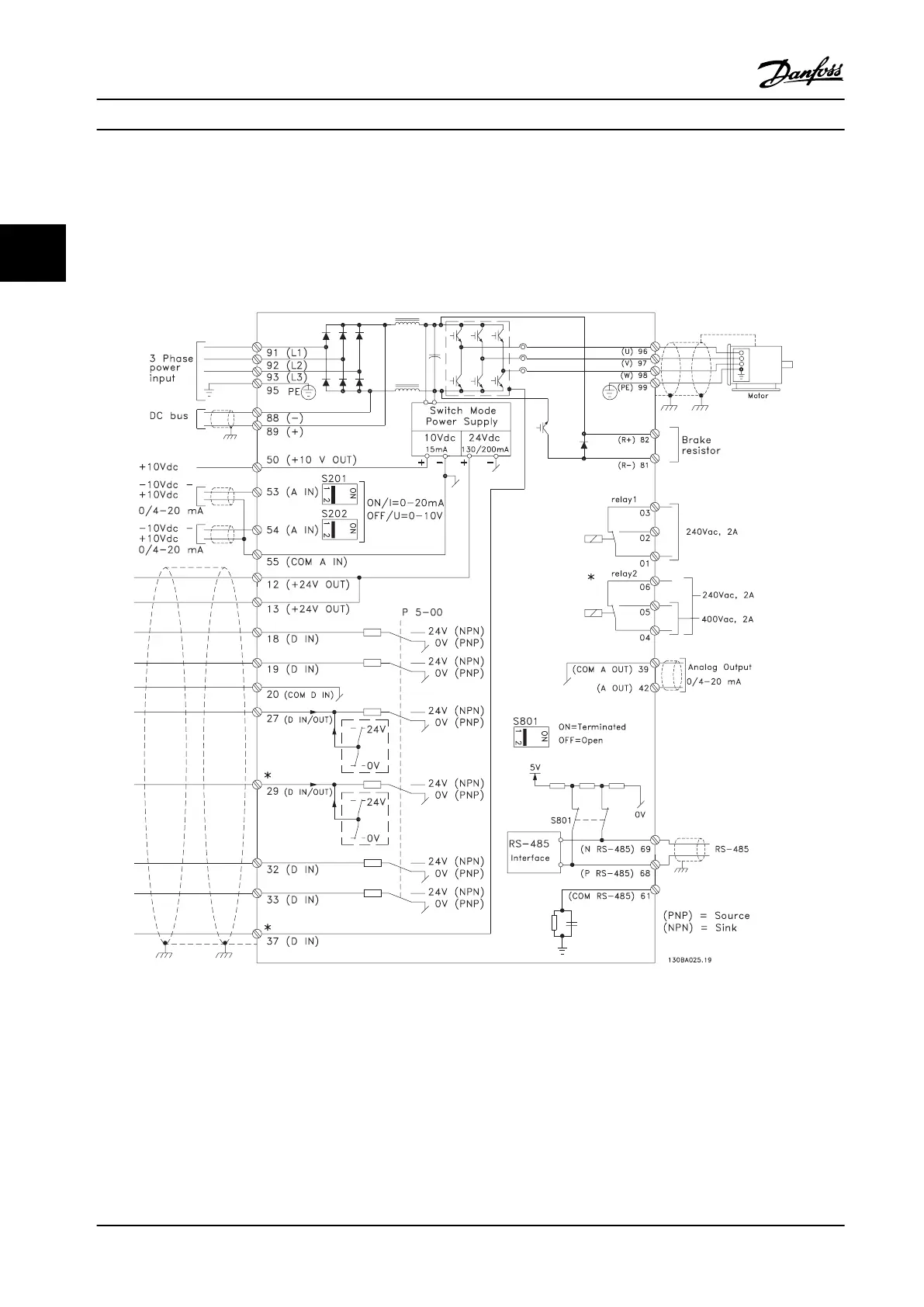
Figure 3.24 Electrical Diagram - Control Cables
Control cables must be shielded/armored. To connect the screen to the frequency converter decoupling plate for control
cables, use a clamp from the accessory bag.
How to Install
VLT
®
Compressor Drives CDS 302/CDS 303
24 Danfoss A/S © Rev. 2013-07-03 All rights reserved. MG34M422
33