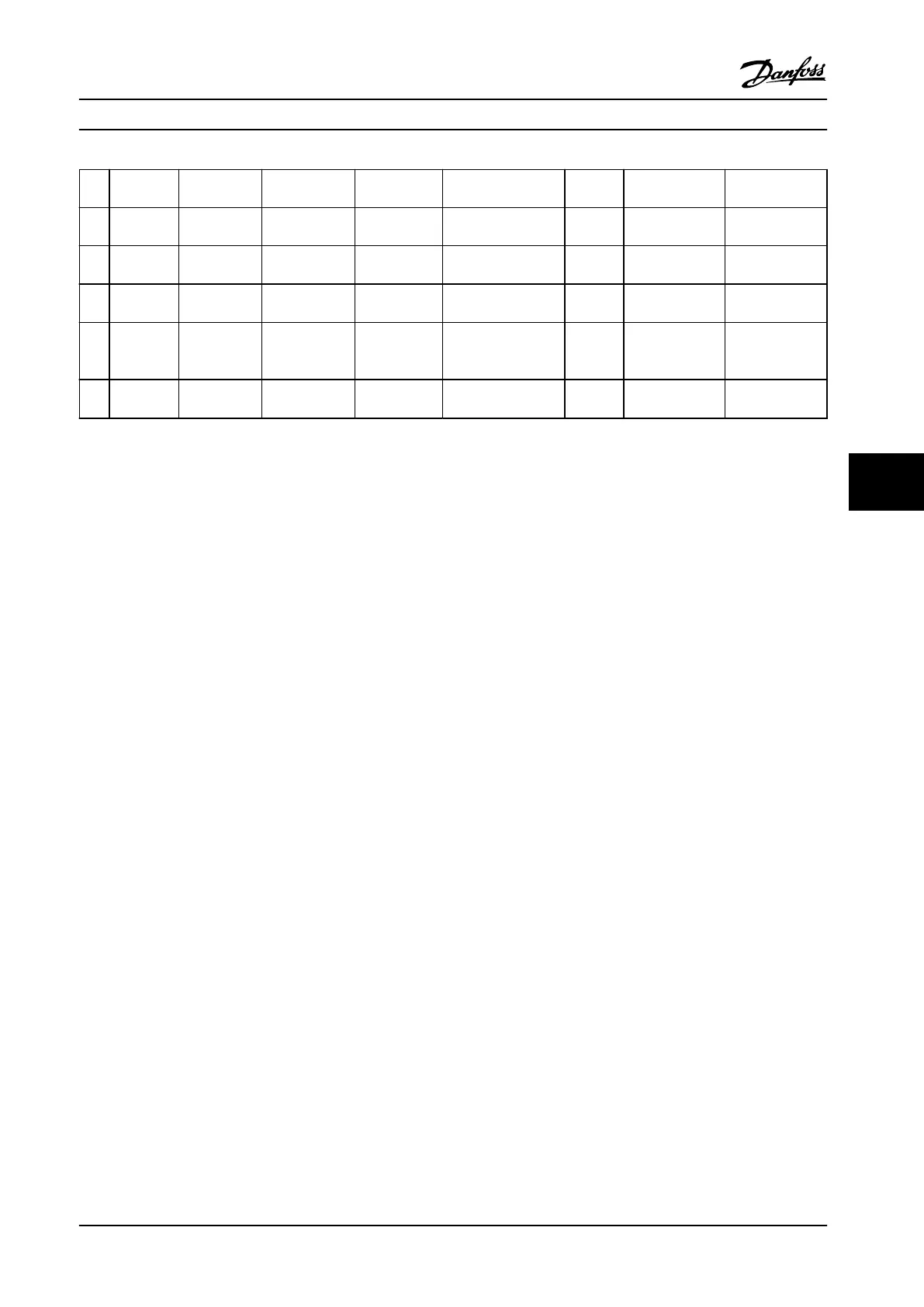
Bit Hex Dec Alarm Word Alarm Word 2 Warning Word Warning
Word 2
Extended
Status Word
Extended
Status Word 2
27 08000000 134217728 Brake IGBT
(A27)
reserved Voltage Limit (W64) reserved Unused Firemode Limit
Exceed
28 10000000 268435456 Option Change
(A67)
reserved Encoder loss (W90) reserved Unused FlyStart active
29 20000000 536870912 Drive
Initialized(A80)
Encoder loss
(A90)
Output freq. lim.
(W62)
BackEMF
too High
Unused
30 40000000 1073741824 Safe Stop (A68) PTC Thermistor
(A74)
Safe Stop (W68) PTC
Thermist
or (W74)
Unused
31 80000000 2147483648 Mech. brake
low (A63)
Dangerous
failure (A72)
Extended Status
Word
Protection Mode
Table 7.3 Description of Alarm Word, Warning Word and Extended Status Word
The alarm words, warning words and extended status words can be read out via serial bus or optional eldbus for
diagnostics. See also parameter 16-94 Ext. Status Word.
WARNING 1, 10 Volts low
The control card voltage is below 10 V from terminal 50.
Remove some of the load from terminal 50, as the 10 V
supply is overloaded. Max. 15 mA or minimum 590 Ω.
This condition can be caused by a short in a connected
potentiometer or improper wiring of the potentiometer.
Troubleshooting
Remove the wiring from terminal 50. If the warning clears,
the problem is with the customer wiring. If the warning
does not clear, replace the control card.
WARNING/ALARM 2, Live zero error
This warning or alarm only appears if programmed by the
user in parameter 6-01 Live Zero Timeout Function. The
signal on one of the analog inputs is less than 50% of the
minimum value programmed for that input. Broken wiring
or faulty device sending the signal can cause this
condition.
Troubleshooting
Check connections on all the analog input
terminals. Control card terminals 53 and 54 for
signals, terminal 55 common. MCB 101 terminals
11 and 12 for signals, terminal 10 common. MCB
109 terminals 1, 3, 5 for signals, terminals 2, 4, 6
common.
Check that the adjustable frequency drive
programming and switch settings match the
analog signal type.
Perform Input Terminal Signal Test.
WARNING/ALARM 3, No motor
No motor has been connected to the output of the
frequency converter.
WARNING/ALARM 4, Mains phase loss
A phase is missing on the supply side, or the line voltage
imbalance is too high. This message also appears for a
fault in the input rectier on the adjustable frequency
drive. Options are programmed at parameter 14-12 Function
at Mains Imbalance.
Troubleshooting
Check the supply voltage and supply currents to the
adjustable frequency drive.
WARNING 5, DC link voltage high
The intermediate circuit voltage (DC) is higher than the
high voltage warning limit. The limit is dependent on the
adjustable frequency drive voltage rating. The unit is still
active.
WARNING 6, DC link voltage low
The intermediate circuit voltage (DC) is lower than the low
voltage warning limit. The limit is dependent on the
adjustable frequency drive voltage rating. The unit is still
active.
WARNING/ALARM 7, DC overvoltage
If the intermediate circuit voltage exceeds the limit, the
frequency converter trips after a time.
Troubleshooting
Connect a brake resistor
Extend the ramp time
Change the ramp type
Activate the functions in parameter 2-10 Brake
Function
Increase parameter 14-26 Trip Delay at Inverter
Fault
If the alarm/warning occurs during a power sag,
use kinetic back-up (parameter 14-10 Line Failure)
Troubleshooting Operating Instructions
MG34M422 Danfoss A/S © Rev. 2013-07-03 All rights reserved. 153
7 7