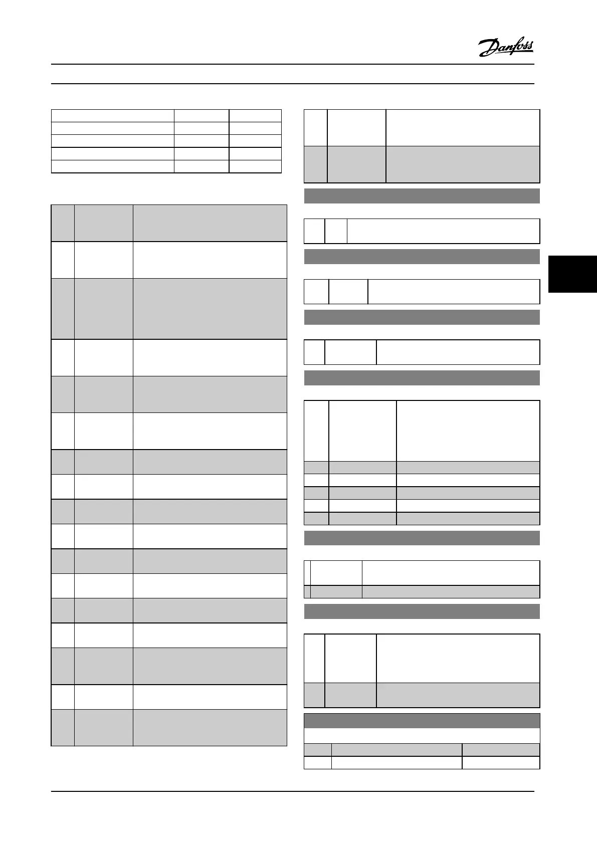
Preset ramp bit 1 0
Ramp 1 0 0
Ramp 2 0 1
Ramp 3 1 0
Ramp 4 1 1
Table 6.7 Ramp Bits
[36] Mains failure
inverse
Activates parameter 14-10 Mains Failure.
Mains failure inverse is active in the
Logic .0. situation.
[39] Day/Night
Control
Reduce the max. frequency with the
setting in parameter 28-74 Night Speed
Drop [RPM].
[41] Latched
Precise Stop
inverse
Sends a latched stop signal when the
precise stop function is activated in
parameter 1-83 Precise Stop Function. The
Latched Precise stop inverse function is
available for terminals 18 or 19.
[55] DigiPot
Increase
INCREASE signal to the Digital Potenti-
ometer function described in parameter
group 3-9* Digital Potmeter.
[56] DigiPot
Decrease
DECREASE signal to the Digital Potenti-
ometer function described in parameter
group 3-9* Digital Potmeter
[57] DigiPot Clear Clears the Digital Potentiometer reference
described in parameter group 3-9* Digital
Potmeter
[60] Counter A (Terminal 29 or 33 only) Input for
increment counting in the SLC counter.
[61] Counter A (Terminal 29 or 33 only) Input for
decrement counting in the SLC counter.
[62] Reset Counter
A
Input for reset of counter A.
[63] Counter B (Terminal 29 or 33 only) Input for
increment counting in the SLC counter.
[64] Counter B (Terminal 29 or 33 only) Input for
decrement counting in the SLC counter.
[65] Reset Counter
B
Input for reset of counter B.
[70] Mech. Brake
Feedback
Brake feedback for hoisting applications
[71] Mech. Brake
Feedback inv.
Inverted brake feedback for hoisting
applications
[80] PTC Card 1 All Digital Inputs can be set to [80] PTC
Card 1. However, only one Digital Input
must be set to this choice.
[121] Lead Pump
Alternation
[130] Compressor
Interlock
Use with cascade controller. Logic 1 will
stop the xed speed compressor and give
a warning
[131] Compressor
Interlock
Use with cascade controller. Logic 1 will
stop the xed speed compressor and give
a warning
[132] Compressor
Interlock
Use with cascade controller. Logic 1 will
stop the xed speed compressor and give
a warning
5-10 Terminal 18 Digital Input
Option: Function:
[8] * Start Functions are described under parameter group 5-1*
Digital Inputs
5-11 Terminal 19 Digital Input
Option: Function:
[10] * Reversing Functions are described under parameter group
5-1* Digital Inputs
5-12 Terminal 27 Digital Input
Option: Function:
[2] * Coast inverse Functions are described under parameter
group 5-1* Digital Inputs
5-13 Terminal 29 Digital Input
Option: Function:
Select the function from the available
digital input range and the additional
options [60], [61], [63] and [64].
Counters are used in Smart Logic
Control functions.
[14] * Jog
[60] Counter A (up)
[61] Counter A (down)
[63] Counter B (up)
[64] Counter B (down)
5-14 Terminal 32 Digital Input
Option: Function:
Select the function from the available digital
input range.
No operation Functions are described under 5-1* Digital Inputs
5-15 Terminal 33 Digital Input
Option: Function:
Select the function from the available digital
input range and the additional options [60],
[61], [63] and [64]. Counters are used in
Smart Logic Control functions.
[0] * No operation Functions are described under 5-1* Digital
Inputs
5-19 Terminal 37 Safe Stop
Option: Function:
[1] Safe Stop Alarm
[3] Safe Stop Warning
Parameter Descriptions Operating Instructions
MG34M422 Danfoss A/S © Rev. 2013-07-03 All rights reserved. 65
6
6