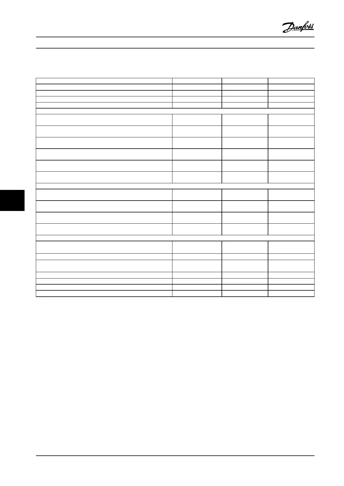
8.1.2 Mains Supply 3x380-480 V AC
P15K P18K P22K
High/Normal Load
1)
NO NO NO
Typical shaft output [HP/kW] 25/18.5 30/22 40/30
Enclosure IP20 B3 B4 B4
Enclosure IP21, IP55, IP66 B1 B2 B2
Output current
Continuous
(3 x 380-440 V) [A]
37.5 44 61
Intermittent (60 s overload)
(3 x 380-440 V) [A]
41.3 48.4 67.1
Continuous
(3 x 441-500 V) [A]
34 40 52
Intermittent (60 s overload)
(3 x 441-500 V) [A]
37.4 44 57.2
Continuous kVA
(400 V AC) [kVA]
26 30.5 42.3
Continuous kVA
(460 V AC) [kVA]
27.1 31.9 41.4
Max. input current
Continuous
(3 x 380-440 V) [A]
34 40 55
Intermittent (60 s overload)
(3 x 380-440 V ) [A]
37.4 44 60.5
Continuous
(3 x 441-500 V) [A]
31 36 47
Intermittent (60 s overload)
(3 x 441-500 V) [A]
34.1 39.6 51.7
Additional specications
IP21, IP55, IP66 max. cable cross-section
5)
(mains, brake, load sharing) [mm
2
(AWG)]
2)
16, 10, 16 (6, 8, 6) 35,-,-(2,-,-) 35,-,-(2,-,-)
IP21, IP55, IP66 max. cable cross-section
5)
(motor) [mm
2
(AWG)]
2)
10, 10,- (8, 8,-) 35, 25, 25 (2, 4, 4) 35, 25, 25 (2, 4, 4)
IP20 max. cable cross-section
5)
(mains, brake, motor and load sharing)
10, 10,- (8, 8,-) 35,-,-(2,-,-) 35,-,-(2,-,-)
Estimated power loss at rated max. load [W]
4)
465 525 739
Weight, enclosure IP20 [lbs/kg] 26.46/12 51.8/23.5 51.8/23.5
Weight, enclosure IP21, IP55, IP66 [lbs/kg] 50.4/23 59.5/27 59.5/27
Eciency
4)
0.98 0.98 0.98
Table 8.2 Mains Supply 3x380-480 V AC
For fuse ratings, see chapter 3.4.1 Fuses
1) Normal overload = 110% torque during 60 s.
2) American Wire Gauge.
3) Measured using 5 m screened motor cables at rated load and rated frequency.
4) The typical power loss is at nominal load conditions and expected to be within
±
15% (tolerence relates to variety in voltage and
cable conditions).
Values are based on a typical motor eciency (e2/e3 border line). Motors with lower eciency will also add to the power loss in the
frequency converter and vice versa.
If the switching frequency is increased compared to the default setting, the power losses may rise signicantly.
LCP and typical control card power consumptions are included. Further options and customer load may add up to 30 W to the losses.
(Though typical only 4 W extra for a fully loaded control card, or options for slot A or slot B, each).
Although measurements are made with state of the art equipment, some measurement inaccuracy must be allowed for (
±
5%).
5) The three values for the max. cable cross section are for single core, exible wire and exible wire with sleeve, respectively.
General Specications
VLT
®
Compressor Drives CDS 302/CDS 303
162 Danfoss A/S © Rev. 2013-07-03 All rights reserved. MG34M422
88