13-16 RS-FF Operand R
Option: Function:
[100] RS Flipop 6
[101] RS Flipop 7
6.10.5 13-2* Timers
Use the result (TRUE or FALSE) from timers directly to
dene an event (see parameter 13-51 SL Controller Event), or
as boolean input in a logic rule (see parameter 13-40 Logic
Rule Boolean 1, parameter 13-42 Logic Rule Boolean 2 or
parameter 13-44 Logic Rule Boolean 3). A timer is only FALSE
when started by an action (i.e. [29] Start timer 1) until the
timer value entered in this parameter is elapsed. Then it
becomes TRUE again.
All parameters in this parameter group are array
parameters with index 0 to 2. Select index 0 to program
Timer 0, select index 1 to program Timer 1, and so on.
13-20 SL Controller Timer
Range: Function:
Size
related*
[ 0.000 -
0.000 ]
Enter the value to dene the duration of
the FALSE output from the programmed
timer. A timer is only FALSE if it is
started by an action (i.e. [29] Start timer
1) and until the given timer value has
elapsed.
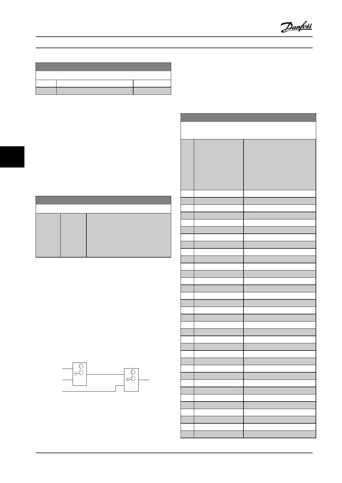
6.10.6 13-4* Logic Rules
Combine up to 3 boolean inputs (TRUE/FALSE inputs) from
timers, comtors, digital inputs, status bits and events using
the logical operators AND, OR, and NOT. Select boolean
inputs for the calculation in parameter 13-40 Logic Rule
Boolean 1, parameter 13-42 Logic Rule Boolean 2 and
parameter 13-44 Logic Rule Boolean 3. Dene the operators
used to logically combine the selected inputs in
parameter 13-41 Logic Rule Operator 1 and
parameter 13-43 Logic Rule Operator 2.
. . .
. . .
. . .
. . .
Par. 13-43
Logic Rule Operator 2
Par. 13-41
Logic Rule Operator 1
Par. 13-40
Logic Rule Boolean 1
Par. 13-42
Logic Rule Boolean 2
Par. 13-44
Logic Rule Boolean 3
130BB673.10
Figure 6.18 Logic Rules
Priority of calculation
The results of parameter 13-40 Logic Rule Boolean 1,
parameter 13-41 Logic Rule Operator 1 and
parameter 13-42 Logic Rule Boolean 2 are calculated rst.
The outcome (TRUE/FALSE) of this calculation is combined
with the settings of parameter 13-43 Logic Rule Operator 2
and parameter 13-44 Logic Rule Boolean 3, yielding the nal
result (TRUE/FALSE) of the logic rule.
13-40 Logic Rule Boolean 1
Array [6]
Option: Function:
[0] FALSE Select the rst boolean (TRUE or
FALSE) input for the selected logic
rule.
See parameter 13-01 Start Event
([0] - [61]) and
parameter 13-02 Stop Event ([70] -
[75]) for further description.
[1] TRUE
[2] Running
[3] In range
[4] On reference
[5] Torque limit
[6] Current Limit
[7] Out of current range
[8] Below I low
[9] Above I high
[10] Out of speed range
[11] Below speed low
[12] Above speed high
[13] Out of feedb. range
[14] Below feedb. low
[15] Above feedb. high
[16] Thermal warning
[17] Mains out of range
[18] Reverse
[19] Warning
[20] Alarm (trip)
[21] Alarm (trip lock)
[22] Comparator 0
[23] Comparator 1
[24] Comparator 2
[25] Comparator 3
[26] Logic rule 0
[27] Logic rule 1
[28] Logic rule 2
[29] Logic rule 3
[30] SL Timeout 0
[31] SL Timeout 1
[32] SL Timeout 2
[33] Digital input DI18
[34] Digital input DI19
Parameter Descriptions
VLT
®
Compressor Drives CDS 302/CDS 303
94 Danfoss A/S © Rev. 2013-07-03 All rights reserved. MG34M422
6
6