NOTICE!
The DC-brake Function is not operational before any
Start Function has completed. In case of an emergency
stop before the starting sequence has completed then
the compressor may rotate reverse for a short moment
after stop. Under normal circumstances, the Short Cycle
Protection feature ensures the correct sequence.
28-40 Reverse Protection Control
Option: Function:
Activate a DC-brake current when the motor is
stopped. The current level is dened in
parameter 28-41 DC Brake Current. Not
recommended for Piston compressors.
[0] * Disabled
[1] Enabled
28-41 DC Brake Current
Range: Function:
90% * [0 – max motor
current ]
Set the DC-brake current as percentage
of the rated motor current in
parameter 1-24 Motor Current.
28-42 DC Braking Time
Range: Function:
2.0 s* [0 – 60.0 s] Set the duration of the DC-brake current.
28-43 DC Brake Cut-in Speed [RPM]
Range: Function:
700 RPM
‘0’ = O*
[0 – max
motor speed]
Set the speed where the DC-brake
Current should cut in. The speed
must be higher than 0 RPM for the
DC-brake to activate before the
motor is coasted at 0 RPM to prevent
a reverse rotation.
6.15.6 28-5* Load Prole
The Load Proler is used to get a graphical presentation of
the load pattern a cooling system has been subjected to
over the last 6 months. The system load is assumed to be
proportional to the compressor speed, and the Load
Proler measures the load as the running hours spent
operating within certain speed intervals.
The speed intervals are calculated based on
parameter 4-11 Motor Speed Low Limit [RPM]
(parameter 4-13 Motor Speed High Limit [RPM]) and
parameter 4-13 Motor Speed High Limit [RPM]
(parameter 4-14 Motor Speed High Limit [Hz]) to match 0%,
25%, 50%, 75% and 100% loads as good as possible. The
speed intervals are denoted “O”, “Low”, “Med.”, “High” and
“Full” and are calculated in the following manner:
Δ = MotorSpeedHighLimit − MotorSpeed LowLimit
O: Speed = 0
Low:
MotorSpeedLowLimit ≤ Speed
< MotorSpeedLowLimit + Δ/6
Med.MotorSpeed
LowLimit + Δ/6 ≤ Speed < MotorSpeedLowLimit + Δ/2
High:
MotorSpeed
LowLimit + Δ/2 ≤ Speed < MotorSpeedLowLimit + 5 × Δ /6
Full:
MotorSpeed
LowLimit + 5 × Δ/6 ≤ Speed ≤ MotorSpeedHighLimit
For example, if 4-11 Motor Speed High Limit is 5400 RPM
and Motor Speed Low Limit is 1800 RPM the four calculated
intervals become
Low: 1800 RPM ≤ speed < 2350 RPM
Med: 2350 RPM ≤ speed < 3450 RPM
High: 3450 RPM ≤ speed < 4550 RPM
Full: 4550 RPM ≤ speed ≤ 5400 RPM
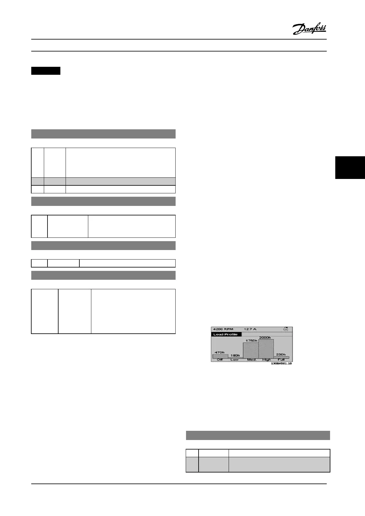
The
prole is presented on the LCP as a histogram. In each
speed interval, the indicated running time is accurate to
within 1 hour.
Figure 6.39 Load Prole
If [O] is pressed on the LCP, the Load Prole is not
updated.
28-50 Reset Load Prole
Option: Function:
[0] * Do not reset No function
[1] Reset Clears the measured running time in all ve
speed intervals.
Parameter Descriptions Operating Instructions
MG34M422 Danfoss A/S © Rev. 2013-07-03 All rights reserved. 125
6
6