reverse. The reversing signal only changes the
direction of rotation. It does not activate the
start function. Select both directions in
parameter 4-10 Motor Speed Direction. The
function is not active in process closed loop.
[11] Start
reversing
Used for start/stop and for reversing on the
same wire. Signals on start are not allowed at
the same time.
[12] Enable
start
forward
Rotates motor shaft clockwise at start.
[13] Enable
start
reverse
Rotates motor shaft counterclockwise at start.
[14] Jog (Default Digital input 29): Use to activate jog
speed. See parameter 3-11 Jog Speed [Hz].
[15] Preset
reference
on
Shifts between external reference and preset
reference. It is assumed that [1] External/preset
has been selected in parameter 3-04 Reference
Function. Logic '0' = external reference active;
logic '1' = one of the eight preset references is
active.
[16] Preset ref
bit 0
Preset ref. bit 0,1, and 2 enables a choice
between one of the eight preset references
according to Table 6.5.
[17] Preset ref
bit 1
Same as Preset ref bit 0 [16].
[18] Preset ref
bit 2
Same as Preset ref bit 0 [16].
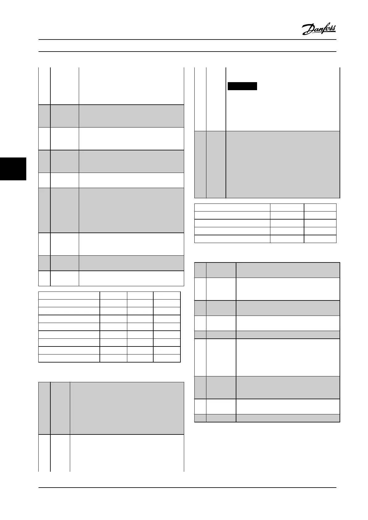
Preset ref. bit 2 1 0
Preset ref. 0 0 0 0
Preset ref. 1 0 0 1
Preset ref. 2 0 1 0
Preset ref. 3 0 1 1
Preset ref. 4 1 0 0
Preset ref. 5 1 0 1
Preset ref. 6 1 1 0
Preset ref. 7 1 1 1
Table 6.5 Reference Bits
[19] Freeze
ref
Freezes the actual reference, which is now the
point of enable/condition for Speed up and Speed
down to be used. If Speed up/down is used, the
speed change always follows ramp 2
(parameter 3-51 Ramp 2 Ramp Up Time and
parameter 3-52 Ramp 2 Ramp Down Time) in the
range 0 - parameter 3-03 Maximum Reference.
[20] Freeze
output
Freezes the actual motor frequency (Hz), which is
now the point of enable/condition for Speed up
and Speed down to be used. If Speed up/down is
used, the speed change always follows ramp 2
(parameter 3-51 Ramp 2 Ramp Up Time and
parameter 3-52 Ramp 2 Ramp Down Time) in the
range 0 to parameter 1-23 Motor Frequency.
NOTICE!
When Freeze output is active, the frequency
converter cannot be stopped via a low [8]
start signal. Stop the frequency converter
via a terminal programmed for [2] Coasting
inverse or [3] Coast and reset, inverse.
[21] Speed
up
Select Speed up and Speed down if digital control
of the up/down speed is desired (motor potenti-
ometer). Activate this function by selecting either
Freeze reference or Freeze output. When Speed up/
down is activated for less than 400 ms the
resulting reference will be increased/ decreased by
0.1 %. If Speed up/ down is activated for more
than 400 ms the resulting reference will follow the
setting in ramping up/ down parameter 3-x1/ 3-x2.
Shut down Catch up
Unchanged speed 0 0
Reduced by %-value 1 0
Increased by %-value 0 1
Reduced by %-value 1 1
Table 6.6 Digital Speed Control
[22] Speed
down
Same as Speed up [21].
[23] Set-up
select bit 0
Select Set-up select bit 0 or Select Set-up
select bit 1 to select one of the 4 set-ups. Set
parameter 0-10 Active Set-up to Multi Set-up.
[24] Set-up
select bit 1
(Default Digital input 32): Same as [23] Set-up
select bit 0.
[28] Catch up Increases or reduces reference value set in
parameter 3-12 Catch up/slow Down Value.
[29] Slow down [28] Same as Catch up.
[30] Counter
input
Precise stop function in parameter 1-83 Precise
Stop Function acts as Counter stop or speed
compensated counter stop with or without
reset. The counter value must be set in
parameter 1-84 Precise Stop Counter Value.
[32] Pulse input Use pulse sequence as either reference or
feedback. Scaling is done in parameter group
5-5* Pulse Input.
[34] Ramp bit 0 Enables a choice between one of the 4 ramps
available, according to Table 6.7.
[35] Ramp bit 1 Same as [34] Ramp bit 0.
Parameter Descriptions
VLT
®
Compressor Drives CDS 302/CDS 303
64 Danfoss A/S © Rev. 2013-07-03 All rights reserved. MG34M422
6
6