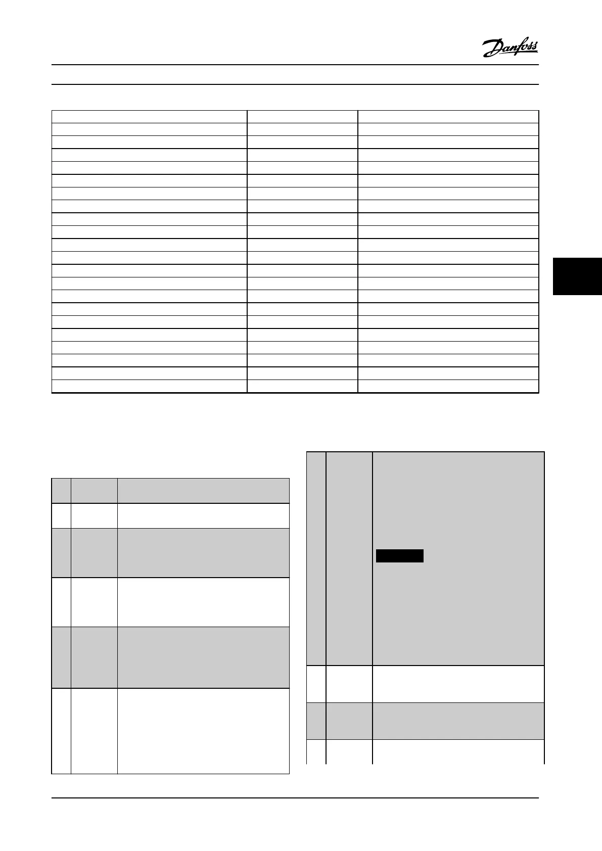
Digital input function Select Terminal
Ramp bit 0 [34] All
Ramp bit 1 [35] All
Mains failure inverse [36] All
Day/night control [39] All
DigiPot Increase [55] All
DigiPot Decrease [56] All
DigiPot Clear [57] All
Counter A (up) [60] 29, 33
Counter A (down) [61] 29, 33
Reset Counter A [62] All
Counter B (up) [63] 29, 33
Counter B (down) [64] 29, 33
Reset Counter B [65] All
Lead pump start [120] All
Lead pump alternation [121] All
Comp. 1 Interlock [130] All
Comp. 2 Interlock [131] All
Comp. 3 Interlock [132] All
Comp. 1 Inv. interlock [139] All
Comp. 2 Inv. interlock [140] All
Comp. 3 Inv. interlock [141] All
Table 6.4 Overview of Digital Inputs
Functions dedicated to only one digital input are stated in the associated parameter.
All digital inputs can be programmed to these functions:
[0] No
operation
No reaction to signals transmitted to the
terminal.
[1] Reset Resets frequency converter after a TRIP/ALARM.
Not all alarms can be reset.
[2] Coast
inverse
(Default Digital input 27): Coasting stop,
inverted input (NC). The frequency converter
leaves the motor in free mode. Logic ‘0’ ⇒
coasting stop.
[3] Coast and
reset
inverse
Reset and coasting stop Inverted input (NC).
Leaves motor in free mode and resets
frequency converter. Logic ‘0’ ⇒ coasting stop
and reset.
[4] Quick stop
inverse
Inverted input (NC). Generates a stop in
accordance with quick-stop ramp time set in
parameter 3-81 Quick Stop Ramp Time. When
motor stops, the shaft is in free mode. Logic ‘0’
⇒ Quick-stop.
[5] DC-brake
inverse
Inverted input for DC braking (NC). Stops
motor by energizing it with a DC current for a
certain time period. See parameter 2-01 DC
Brake Current to parameter 2-03 DC Brake Cut In
Speed [RPM]. The function is only active when
the value in parameter 2-02 DC Braking Time is
dierent from 0. Logic ’0’ ⇒ DC braking.
[6] Stop
inverse
Stop Inverted function. Generates a stop
function when the selected terminal goes from
logical level ‘1’ to ‘0’. The stop is performed
according to the selected ramp time
(parameter 3-42 Ramp 1 Ramp Down Time,
parameter 3-52 Ramp 2 Ramp Down Time,
parameter 3-62 Ramp 3 Ramp down Time,
parameter 3-72 Ramp 4 Ramp Down Time).
NOTICE!
When the frequency converter is at the
torque limit and has received a stop
command, it may not stop by itself. To
ensure that the frequency converter
stops, congure a digital output to [27]
Torque limit & stop and connect this
digital output to a digital input that is
congured as coast.
[8] Start (Default Digital input 18): Select start for a
start/stop command. Logic ‘1’ = start, logic ‘0’
= stop.
[9] Latched
start
The motor starts, if a pulse is applied for min.
2 ms. The motor stops when Stop inverse is
activated.
[10] Reversing (Default Digital input 19). Change the direction
of motor shaft rotation. Select Logic ‘1’ to
Parameter Descriptions Operating Instructions
MG34M422 Danfoss A/S © Rev. 2013-07-03 All rights reserved. 63
6
6