0-12 This Set-up Linked to
Option: Function:
OR
2.
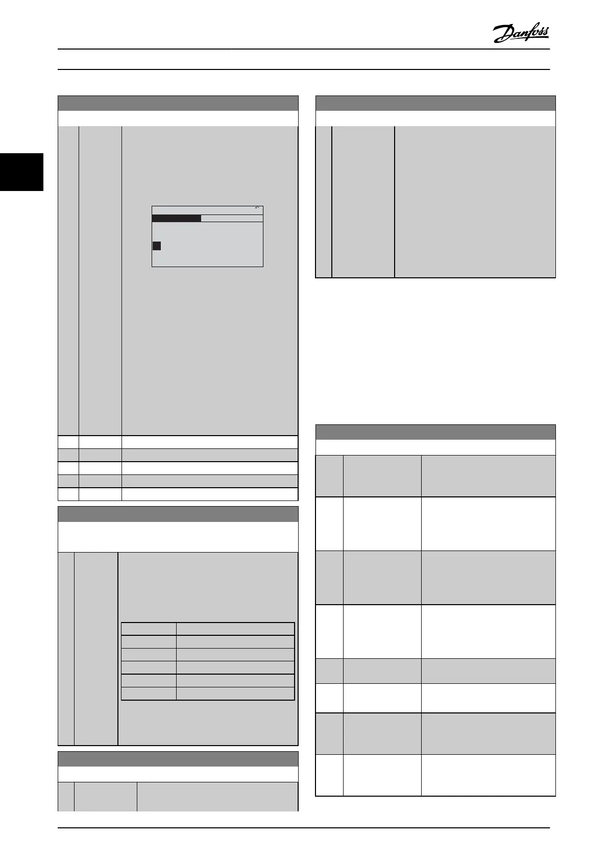
While still in Set-up 1, using 0-50 LCP Copy,
copy Set-up 1 to Set-up 2. Then set 0-12 This
Set-up Linked to to [2] Set-up 2. This will start
the linking process.
130BP076.10
0-12 This Set-up Linked to
0 RPM
0.00A
1(1)
Set-up Handling
0-1*
[2]
Setup 2
Illustration 3.2
After the link is complete, 0-13
Readout: Linked
Set-ups will read {1,2} to indicate that all ‘not
changeable during operation’ parameters are
now the same in Set-up 1 and Set-up 2. If there
are changes to a ‘not changeable during
operation’ parameter, e.g. 1-30 Stator Resistance
(Rs), in Set-up 2, they will also be changed
automatically in Set-up 1. A switch between
Set-up 1 and Set-up 2 during operation is now
possible.
[0] * Not linked
[1] Set-up 1
[2] Set-up 2
[3] Set-up 3
[4] Set-up 4
0-13 Readout: Linked Set-ups
Array [5]
Range: Function:
0 * [0 - 255 ]
View a list of all the set-ups linked by means of
0-12
This Set-up Linked to. The parameter has one
index for each parameter set-up. The parameter
value displayed for each index represents which
set-ups are linked to that parameter set-up.
Index LCP value
0 {0}
1 {1,2}
2 {1,2}
3 {3}
4 {4}
Table 3.2 Example: Set-up 1 and Set-up 2 are
linked
0-14 Readout: Prog. Set-ups / Channel
Range: Function:
0 * [-2147483648
-
2147483647 ]
View the setting of 0-11 Programming Set-
up for each of the four different
0-14 Readout: Prog. Set-ups / Channel
Range: Function:
communication channels. When the
number
is displayed in hex, as it is in the
LCP, each number represents one channel.
Numbers 1-4 represent a set-up number; ‘F’
means factory setting; and ‘A’ means active
set-up. The channels are, from right to left:
LCP, FC-bus, USB, HPFB1.5.
Example: The number AAAAAA21h means
that the FC-bus selected Set-up 2 in
0-11 Programming Set-up, the LCP selected
Set-up 1 and all others used the active set-
up.
3.2.2 0-2* LCP Display
Define the variables displayed in the Graphical Local
Control Panel.
NOTE
Please
refer to 0-37 Display Text 1, 0-38 Display Text 2 and
0-39 Display Text 3 for information on how to write display
texts.
0-20 Display Line 1.1 Small
Option: Function:
Select a variable for display in line
1, left position. Default setting is
application dependent.
[37] Display Text 1 Enables an individual text string to
be
written, for display in the LCP or
to be read via serial communi-
cation.
[38] Display Text 2 Enables an individual text string to
be
written, for display in the LCP or
to be read via serial communi-
cation.
[39] Display Text 3 Enables an individual text string to
be
written, for display in the LCP or
to be read via serial communi-
cation.
[89] Date and Time
Readout
Displays the current date and time.
[953] Profibus Warning
Word
Displays Profibus communication
warnings.
[1005] Readout Transmit
Error
Counter
View the number of CAN control
transmission errors since the last
power-up.
[1006] Readout Receive
Error
Counter
View the number of CAN control
receipt errors since the last power-
up.
Parameter Description
VLT
®
Refrigeration Drive Programming Guide
28 MG16H102 - VLT
®
is a registered Danfoss trademark
33
 Loading...


