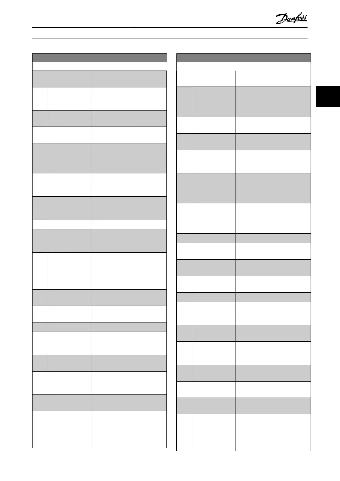
0-20 Display Line 1.1 Small
Option: Function:
[1007] Readout Bus Off
Counter
View the number of Bus Off events
since
the last power-up.
[1013] Warning Parameter View a DeviceNet-specific warning
word.
One sete bit is assigned to
every warning.
[1501] Running Hours View the number of running hours
of
the motor.
[1502] kWh Counter View the mains power consumption
in
kWh.
[1600] Control Word View the Control Word sent from
the
frequency converter via the
serial communication port in hex
code.
[1601] Reference [Unit] Total reference (sum of digital/
analog/preset/bus/freeze
ref./catch
up and slow-down) in selected unit.
[1602] Reference [%] Total reference (sum of digital/
analog/preset/bus/freeze
ref./catch
up and slow-down) in percent.
[1603] Status Word Present status word
[1605] Main Actual Value
[%]
View the two-byte word sent with
the
Status word to the bus Master
reporting the Main Actual Value.
[1609] Custom Readout View the user-defined readouts as
defined
in 0-30 Custom Readout
Unit, 0-31 Custom Readout Min Value
and 0-32 Custom Readout Max
Value.
[1610] Power [kW] Actual power consumed by the
motor
in kW.
[1611] Power [hp] Actual power consumed by the
motor
in HP.
[1612] Motor Voltage Voltage supplied to the motor.
[1613] Frequency Motor frequency, i.e. the output
frequency
from the frequency
converter in Hz.
[1614] Motor current Phase current of the motor
measured
as effective value.
[1615] Frequency [%] Motor frequency, i.e. the output
frequency
from the frequency
converter in percent.
[1616] Torque [Nm] Present motor load as a percentage
of
the rated motor torque.
[1617] Speed [RPM] Motor speed reference. Actual
speed
will depend on slip compen-
sation being used (compensation
set in 1-62 Slip Compensation). If not
used, actual speed will be the value
0-20 Display Line 1.1 Small
Option: Function:
read in the display minus motor
slip.
[1618] Motor Thermal Thermal load on the motor,
calculated
by the ETR function. See
also parameter group 1-9* Motor
Temperature.
[1622] Torque [%] Shows the actual torque produced,
in
percentage.
[1630] DC Link Voltage Intermediate circuit voltage in the
frequency
converter.
[1632] Brake Energy /s Present brake power transferred to
an
external brake resistor.
Stated as an instantaneous value.
[1633] Brake Energy /2 min Brake power transferred to an
external
brake resistor. The mean
power is calculated continuously for
the most recent 120 seconds.
[1634] Heatsink Temp. Present heat sink temperature of
the
frequency converter. The cut-
out limit is 95 ± 5° C; cutting back
in occurs at 70 ± 5° C.
[1635] Inverter Thermal Percentage load of the inverters
[1636] Inv. Nom. Current Nominal current of the frequency
converter
[1637] Inv. Max. Current Maximum current of the frequency
converter
[1638] SL Controller State State of the event executed by the
control
[1639] Control Card Temp. Temperature of the control card.
[1650] External Reference Sum of the external reference as a
percentage,
i.e. the sum of analog/
pulse/bus.
[1652] Feedback[Unit] Reference value from programmed
digital
input(s).
[1653] Digi Pot Reference View the contribution of the digital
potentiometer
to the actual
reference Feedback.
[1654] Feedback 1 [Unit] View the value of Feedback 1. See
also
20-0*.
[1655] Feedback 2 [Unit] View the value of Feedback 2. See
also
20-0*.
[1656] Feedback 3 [Unit] View the value of Feedback 3. See
also
parameter group 20-0*.
[1660] Digital Input Displays the status of the digital
inputs.
Signal low = 0; Signal high
= 1.
Regarding order, see 16-60 Digital
Input. Bit 0 is at the extreme right.
Parameter Description
VLT
®
Refrigeration Drive Programming Guide
MG16H102 - VLT
®
is a registered Danfoss trademark
29
3 3
 Loading...


