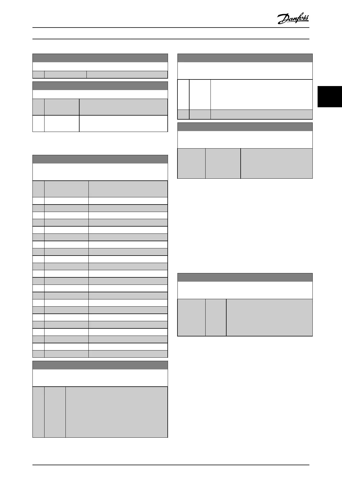
13-02 Stop Event
Option: Function:
[83] Broken Belt
13-03 Reset SLC
Option: Function:
[0] * Do not reset
SLC
Retains programmed settings in all
parameter
group 13 parameters (13-**).
[1] Reset SLC Resets all parameter group 13 parameters
(13-**)
to default settings.
3.10.3 13-1* Comtors
13-10 Comparator Operand
Array [5]
Option: Function:
Select the variable to be monitored
by
the comtor.
[0] * DISABLED
[1] Reference
[2] Feedback
[3] Motor speed
[4] Motor Current
[5] Motor torque
[6] Motor power
[7] Motor voltage
[8] DC-link voltage
[9] Motor Thermal
[10] Drive thermal
[11] Heat sink temp.
[12] Analog input AI53
[13] Analog input AI54
[14] Analog input AIFB10
[15] Analog input AIS24V
[17] Analog input AICCT
[18] Pulse input FI29
[19] Pulse input FI33
[20] Alarm number
[30] Counter A
[31] Counter B
13-11 Comparator Operator
Array [6]
Option: Function:
[0] * <
Select [0]
<
for the result of the evaluation to be
TRUE, when the variable selected in
13-10 Comparator Operand is smaller than the
fixed value in 13-12 Comparator Value. The result
will be FALSE, if the variable selected in
13-10 Comparator Operand is greater than the
fixed value in 13-12 Comparator Value.
13-11 Comparator Operator
Array [6]
Option: Function:
[1] ≈ (equal)
Select [1] ≈
for
the result of the evaluation to be
TRUE, when the variable selected in
13-10 Comparator Operand is approximately equal
to the fixed value in 13-12 Comparator Value.
[2] >
Select [2] >
for the inverse logic of option [0] <.
13-12 Comparator Value
Array [6]
Range: Function:
Size related* [-100000 -
100000
]
Enter the ‘trigger level’ for the
variable that is monitored by this
comtor. This is an array parameter
containing comtor values 0 to 5.
3.10.4 13-2* Timers
Use the result (TRUE or FALSE) from timers
directly
to
define an event (see 13-51 SL Controller Event), or as
boolean input in a logic rule (see 13-40 Logic Rule Boolean
1, 13-42 Logic Rule Boolean 2 or 13-44 Logic Rule Boolean 3).
A timer is only FALSE when started by an action (i.e. [29]
Start timer 1) until the timer value entered in this
parameter is elapsed. Then it becomes TRUE again.
All parameters in this parameter group are array
parameters with index 0 to 2. Select index 0 to program
Timer 0, select index 1 to program Timer 1, and so on.
13-20 SL Controller Timer
Array [8]
Range: Function:
Size related* [ 0 - 0 ] Enter the value to define the duration of
the
FALSE output from the programmed
timer. A timer is only FALSE if it is started
by an action (i.e. [29]vStart timer 1) and
until the given timer value has elapsed.
3.10.5 13-4* Logic Rules
Combine up to three boolean inputs (TRUE/FALSE inputs)
from
timers, comtors, digital inputs, status bits and events
using the logical operators AND, OR, and NOT. Select
boolean inputs for the calculation in 13-40 Logic Rule
Boolean 1, 13-42 Logic Rule Boolean 2 and 13-44 Logic Rule
Boolean 3. Define the operators used to logically combine
the selected inputs in 13-41 Logic Rule Operator 1 and
13-43 Logic Rule Operator 2.
Parameter Description
VLT
®
Refrigeration Drive Programming Guide
MG16H102 - VLT
®
is a registered Danfoss trademark
87
3 3
 Loading...


