EasyManuals Logo

Danfoss VLT series User Manual

Danfoss VLT series
98 pages
To Next Page IconTo Next Page
To Previous Page IconTo Previous Page
Page #43 background imageLoading...
Page #43 background image
2
7
U/T1 96
FASTENER TORQUE: M10 19 Nm (14 FT-LB)
V/T2 97 W/T3 98 U/T1 96
FASTENER TORQUE: M10 19 Nm (14 FT-LB)
V/T2 97 W/T3 98 U/T1 96
FASTENER TORQUE: M10 19 Nm (14 FT-LB)
V/T2 97 W/T3 98
6
8, 9
4
3
1
5
130BA862.12
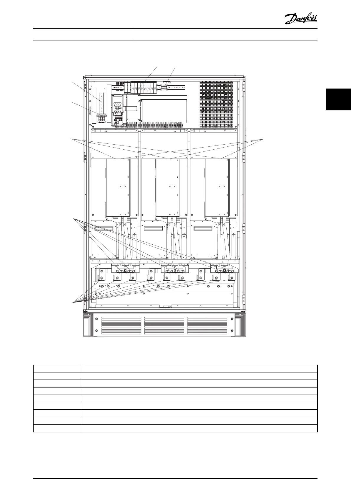
1 NAMUR fuse. See Table 3.25 for part numbers.
2 NAMUR terminals (optional)
3 External temperature monitoring
4 AUX relay (01, 02, 03, 04, 05, 06)
5 AUX fan (100, 101, 102, 103)
6 Motor connection, 1 per module T1 (U), T2 (V), T3 (W)
7 Brake 81 (-R), 82 (+R)
8 Fan fuses. See Table 3.22 for part numbers.
9 SMPS fuses. See Table 3.21 for part numbers.
Illustration 3.39 Inverter Cabinet, Enclosure Sizes F12 and F13
How to Install Operating Instructions
MG34Q402 Danfoss A/S © 04/2016 All rights reserved. 41
3 3

Table of Contents

Other manuals for Danfoss VLT series

Questions and Answers:

Question and Answer IconNeed help?

Do you have a question about the Danfoss VLT series and is the answer not in the manual?

Danfoss VLT series Specifications

General IconGeneral
SeriesVLT
CategoryDC Drives
Output Voltage0-100% of input voltage
Protection FeaturesOvervoltage, Undervoltage, Overcurrent, Overtemperature, Short Circuit, Ground Fault
Communication InterfacesProfibus, CANopen
Enclosure RatingIP20, IP21, IP55, IP66
Cooling MethodForced Air Cooling, Convection Cooling
Control ModeSensorless Vector, Closed Loop Vector
Ambient Temperature-10°C to +50°C (14°F to 122°F)

Related product manuals