130BC250.10
2, 3, 4
5
6
I3 I4I2
I1
1
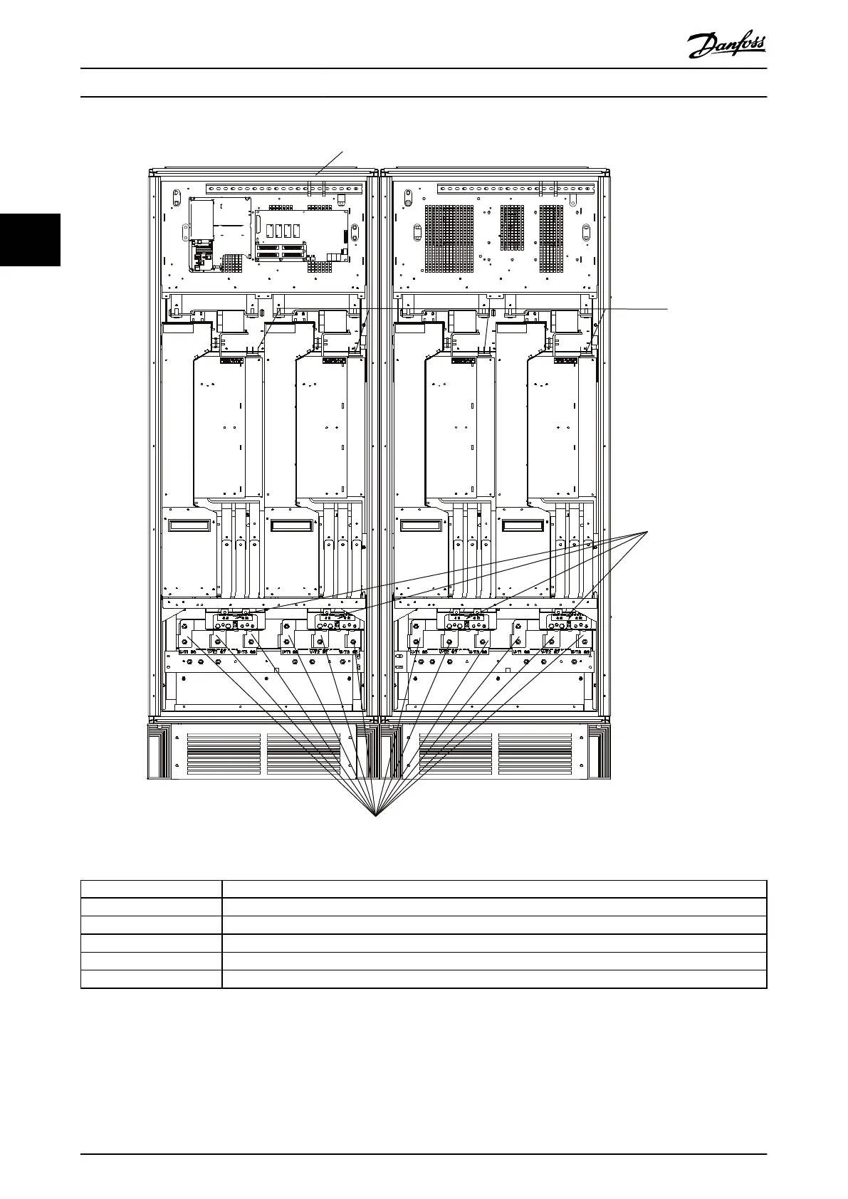
1 Auxiliary relay (01, 02, 03, 04, 05, 06)
2 AUX fan (100, 101, 102, 103)
3 Fan fuses. See Table 3.22 for part numbers.
4 SMPS fuses. See Table 3.21 for part numbers.
5 Brake 81 (-R), 82 (+R)
6 Motor connection, 1 per module T1 (U), T2 (V), T3 (W)
Illustration 3.40 Inverter Cabinet, Enclosure Size F14 and F15
How to Install
VLT
®
AutomationDrive FC 302
42 Danfoss A/S © 04/2016 All rights reserved. MG34Q402
33