DKM-411 User Manual Rev_01 Firmware V-1.0
K46D03-EN - 45 -
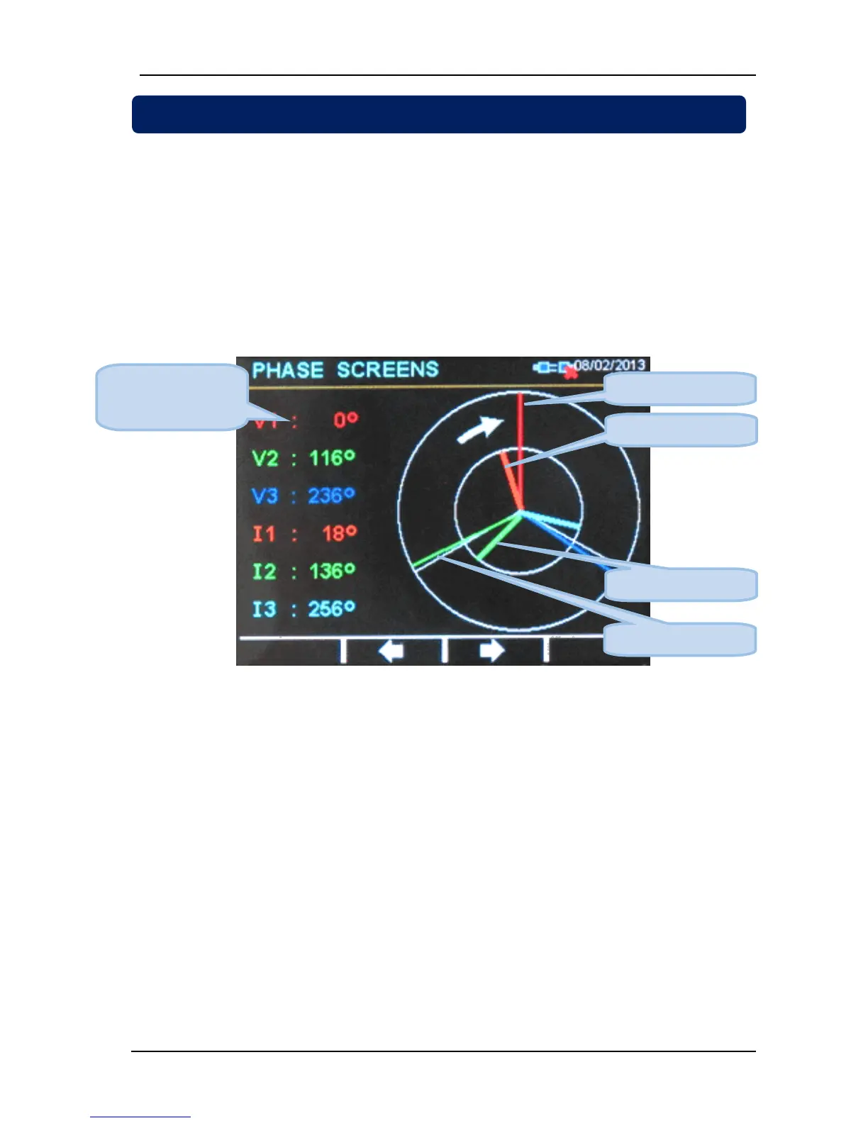
The unit offers a Phasor diagram display presenting the phasing of all voltage and current inputs.
The reference phase is the voltage input V1 (L1-N voltage). This is the long vertical segment drawn in red
color.
The white arrow in the diagram shows the correct rotation direction. Usually in a 3 phase system, the
voltage V2 (long segment in green color) is 120 degrees behind (lagging) the voltage V1.
The voltage V3 (long segment in blue color) will be 240 degrees behind V1.
The currents are represented with shorter and thicker segments. They may be lagging (inductive load) or
leading (capacitive load) the related phase voltage. In our example below, currents are lagging by
approximately 20 degrees. Thus our sample load is inductive.
Phasor Diagram Display