RAPID CONFIGURATION
1
AS9132A AND AIM DPM VERIFICATION:
PG 6000
CAB-MS01
CBX
Main Interface
Host
Matrix 400™
BK-4410
LT-410
Code Surface
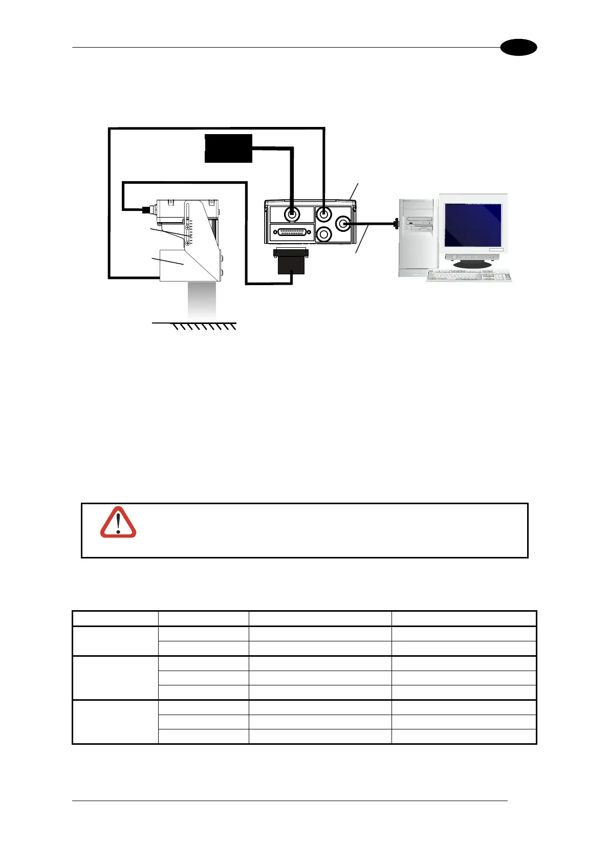
Figure 4 – Matrix 400™ in ISO/IEC 15415 and ISO/IEC 15416 Verifier Layout
1. Connect the Matrix 400™ to the CBX connection box.
2. Connect the selected LT-XXX lighting system to the CBX connection box according to the
wiring table below.
3. Connect the CBX to the PG600x power supply unit.
4. Connect the selected communication interface to the Host.
5. Connect the main power supply and switch on the system.
CAUTION
Power is available directly to the Illuminator, independently from the
Power Supply Switch inside the CBX.
Below is a table summarizing the various External Illuminator wiring and power requirements:
Illuminator Wire Color CBX/Matrix Signal Meaning
LT-100 Red Vdc 10 to 30 Vdc
LT-200 Black GND Ground
LT-300 Brown Vdc 10 to 30 Vdc
Black GND Ground
Yellow/Green Earth Shield/Earth Ground
LT-210, LT-314, White Vdc 24 Vdc
LT-316, LT-410 Black GND Ground
LT-510, LT-511 Shield Earth Shield/Earth Ground
5