EasyManuals Logo

Datalogic SC6000 User Manual

Datalogic SC6000
76 pages
To Next Page IconTo Next Page
To Previous Page IconTo Previous Page
Page #22 background imageLoading...
Page #22 background image
SC6000
12
2
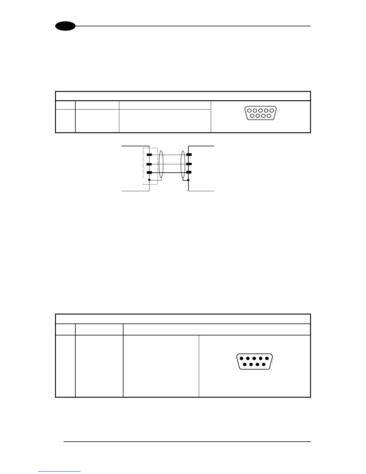
2.4.2 Auxiliary Interface
The auxiliary serial interface is equipped with RS232 interface connections. The interface
can be enabled or disabled through the Genius™ configuration program.
The following pins of the 9-pin connector are used for RS232 interface connection:
9-pin D-sub Female Connector Pinout
Pin
Name
Function
5
1
9
6
9-pin D-sub Female Connector
2
TX
Transmit
3
RX
Receive
5
GND
Ground
SC6000
USER INTERFACE (Laptop)
5
GND
Signal Ground
TXD
RXAUX
3
RXD
TXAUX
2
Shield
Figure 15 RS232 Auxiliary Interface Connections
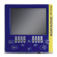
2.4.3 Modem Interface
SC6000 offers a dedicated 9-pin port for a Modem connection. The modem connection
allows a Host to remotely control the reading station. The connections to modem can be
made as follows:
through the PWO (in which case the modem is installed internally to the PWO and a
CAB-SC6103 cable connects the modem from the PWO to the SC6000)
directly to the SC6000
See also par. 2.5.1.
9-pin D-sub Male Connector Pinout
Pin
Name
Function
1
CD
Carrier detect
1
5
6
9
9-pin D-sub Male Connector
2
RX
Receive
3
TX
Transmit
4
DTR
Data terminal ready
5
GND
Ground
6
DSR
Data set ready
7
RTS
Request to send
8
CTS
Clear to send
9
RI
Ring indicator

Other manuals for Datalogic SC6000

Questions and Answers:

Question and Answer IconNeed help?

Do you have a question about the Datalogic SC6000 and is the answer not in the manual?

Datalogic SC6000 Specifications

General IconGeneral
BrandDatalogic
ModelSC6000
CategoryController
LanguageEnglish

Related product manuals