A-Class 137
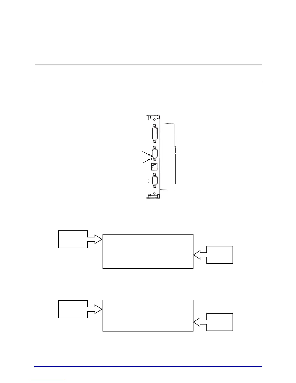
GPIO A
Signals
GPIO B
Signals
GPIO A
Signals
GPIO B
Signals
Indicators and Monitors
Real-time verification of settings and activity of the GPIO ports is available via displayed and
printed information:
;
Unused, non-connected inputs and outputs will have an indeterminate state and
assume a value of 1 or 0.
Indicators: Sampled every millisecond, incoming (IN) and outgoing (OUT) signal
activity can be observed on the card, where LED color changes correspond to signal
state changes.
Signal Out
Signal In
Input Monitors: Binary input signal states can be viewed (see Section 4.2.6, TEST
GPIO / MONITOR GPIO INPUT) in the following format:
SOP FEED PAUSE REPRT
1 1 0 0
i1 i2 i3 i4 i5 i6
0 1 0 1 1 1
Output Monitors: Binary output signal states can be viewed (see Section 4.2.6, TEST
GPIO / MONITOR GPIO OUTPUT) in the following format:
EP RL SR MO RO DR OF
0 0 0 0 0 0 0
o1 o2 o3 o4 o5 o6
0 0 0 0 0 0