Technical Manual
12
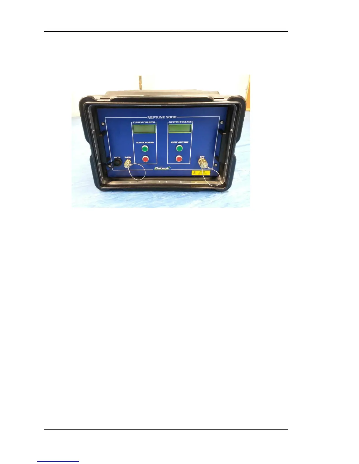
Figure 2: Topside Control Box
Topside Control Box
Description
The Topside Control Box, illustrated in Error! Reference source not found.,
is housed in a shock mounted IP65 enclosure. It contains the main system
Topside Transformer, Power Supply Board, Telemetry Board, Data Coupling
Board and LCD Displays.
The Topside Control Box has three connectors on the front. These are a
network connection for Ethernet, a 3 pin male for mains power in, and a 3 pin
female for high voltage power out and the superimposed data. There are also
two LCD displays, one for system current and one for the system high voltage,
and four illuminated push button switches. Three cables are supplied for use
with the Topside Control Box, Mains Supply, PC Ethernet and High Voltage
Deck Umbilical. Only these supplied cables should be used with the system.
Always ensure that all the cables are fitted correctly before supplying power to
the Topside Control Box. When power is supplied, the “MAINS POWER” red
push button switch will illuminate indicating that the supply is available and
the Topside Control Box is in Standby mode. To switch on the Topside Control
Box, press the “MAINS POWER” green push button switch. The LCD displays
will switch on, the “MAINS POWER” green push button switch will illuminate,
the “MAINS POWER” red push button switch will go out and the “HIGH
VOLTAGE” red push button switch will illuminate. The Topside Control Box is
now live but the CPT high voltage supply is not on.