Specification
Supply Input: 240Vac
Supply Input Current: 2A
Low Voltage Outputs: +5VDC, +12VDC +/-15VDC
Low Voltage Cone Output: +/-15VDC
FS2: Not fitted
FS3: 2A(T)
Subsea Connector PCB
Overview
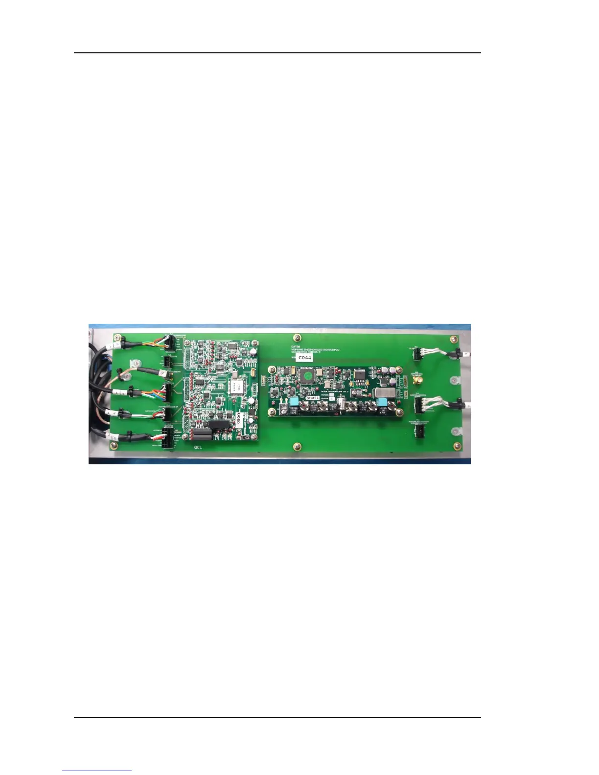
The Subsea Connector PCB provides the necessary connectors to connect all
the sensors within the system to the Subsea Micro controller. The Subsea
Connector PCB is illustrated in figure 18.
Two circuit boards are fitted to this board; the Subsea Microcontroller and the
Subsea Telemetry PCB.
Circuit Description
Power is supplied to the board on connectors PL6 (Telemetry power) and PL7
(Controller/Cone). The Altimeters are connected to PL3 (Optional) and
communicate with the Subsea Microcontroller on a RS232 serial link. The
penetration and cone up sensors are connected to PL4. The Hydrostatic sensor
is connected to PL2. The Cone is connected to PL1 and is wired for digital
cones. The telemetry data link is connected to SK1 which is a micro coax
connector. The inverter control functions are connected to PL5 using the
RS485 connections
Depending upon the Issue of Telemetry board being used, it connects to the
Connector PCB using either plugs PL13A, PL14A, and PL15A (Issue B