Technical Manual
20
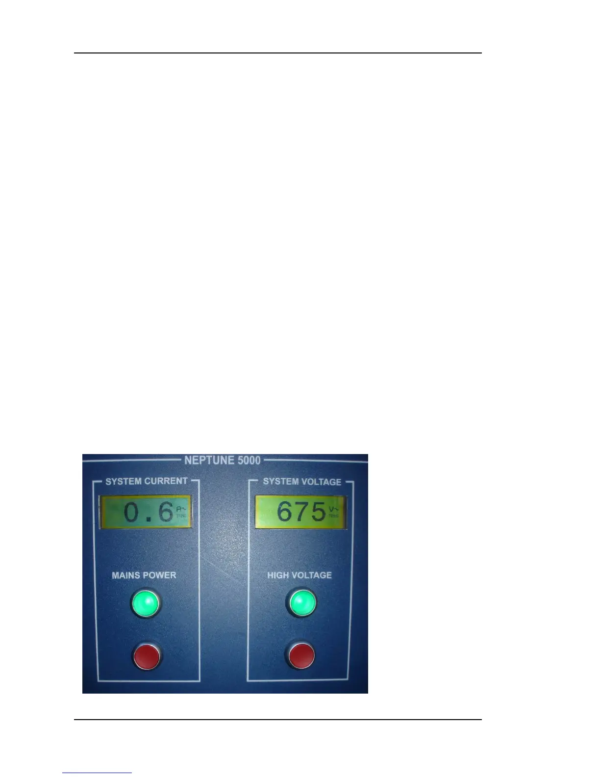
Figure 8: LCD Voltmeter and Ammeter Displays
“Tx0” when a character is transmitted to the Topside PC; “Tx1” when a
character is transmitted to the Subsea Telemetry Board; “Rx1” when a
character is received from the Subsea Telemetry Board.
Automatic Tuning
The automatic telemetry tuning sequence takes approximately 5 seconds if
both telemetry boards are active and there are no hardware faults. During
tuning, the “Tx1” LED is illuminated, while the “Rx1” LED turns on and off at
about 1 second intervals. Once two-way communication has been established,
both “Tx1” and “Rx1” will blink very rapidly at about equal intensity, showing
that handshake messages are being transmitted and received. After a
successful tuning sequence the Topside Telemetry Board stores its tuning
results together with those obtained from the Subsea Telemetry Board. These
results are displayed on the Engineering Screen of the Neptune 5000 program.
(“Level” is a code related to the receiving circuit threshold voltage; “Quality” is
a value corresponding to the number of consecutive valid tuning strings
received while ramping up the threshold voltage – the “Quality” value
decreases as the umbilical length increases.) If the tuning sequence keeps
repeating, it may be that the Subsea Telemetry Board is not powered up or
the umbilical is not connected.
LCD Displays
The Topside control box has two LCD display modules mounted behind
Perspex windows on the front panel. The display modules are factory set up to
display either System Umbilical Voltage or Topside control box Mains Current
input.