Neptune 5000
© Copyright Datem Limited 2014
41
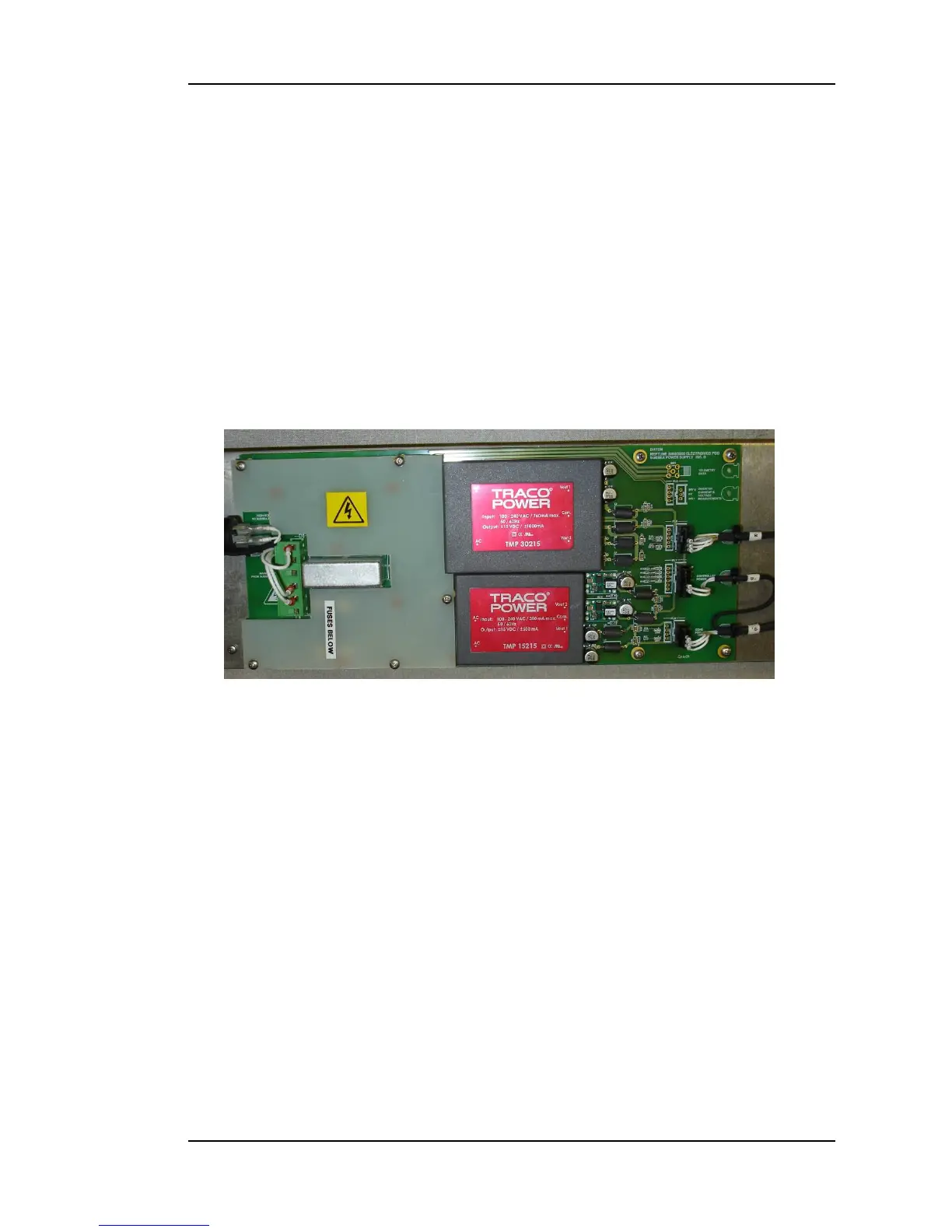
Figure 17: Subsea Power Supply PCB
End Cap and Chassis Assembly Refitting
Refitting the pod is simply the reverse process of removal, but special care
should be taken with ensuring the o-rings are in good condition and
appropriately lubricated with silicone grease. Ensure that none of the assembly
cables or connectors are disturbed whilst lowering the chassis assembly back
into the vessel.
Subsea Power Supply PCB
Overview
The Subsea Power Supply PCB, illustrated in Figure 17, provides the power
needed by the subsea electronics.
Separate supplies are provided for the subsea telemetry PCB, subsea
electronics and the Digital Cone.
Circuit Description
The subsea transformer secondary output is connected to the mains input
screw terminals on PL3. The voltage on these terminals will be at mains
potential 240Vac. The live fed passes though board protection fuse FS1 rated
at 5 amps (acting as a link) and then through FS3 rated at 2 amps. The output
from FS3 feds a mains input filter. A Protective cover is fitted over this part of
the board.
Two AC to DC encapsulated power supply modules provide the necessary low
voltage supplies required by the various subsea boards.
A further DC to DC board DC1 is used to provide 12 volts used by the
controller board. Output filtering is used to ensure stable supplies for all
circuits. Each output voltage has its own LED status indicator (LED1-8)
The telemetry board power supply is output on PL6 +/- 15V
The controller board power supply is output on PL7 +12V
The cone board power supply is output on PL8 +/- 15V