Neptune 5000
© Copyright Datem Limited 2014
73
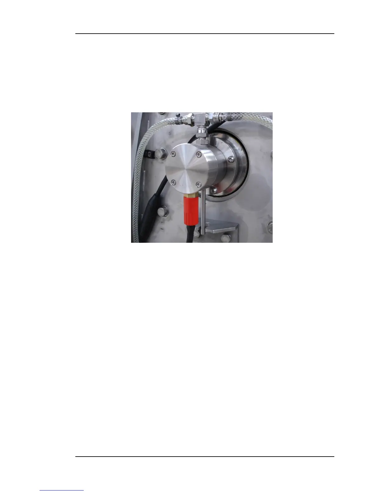
Figure 31: Slip Ring
Slip-ring
The slip-ring assembly, illustrated in figure 31, provides the means of
transferring the cone power and data from the revolving thruster to the
stationary base and electronics pod. The slip ring is fitted to the central drive
shaft by four cap-head bolts. It is oil filled to enable pressurisation, with the
pressure compensator mounted on the front support pedestal and a hydraulic
hose connecting the two items.
Specification
Assembly
The slip ring assembly is below in Drawing 1534-01-GA. This drawing provides
a representation of the main parts that make up the assembly, and the way in
which they fit together. There are no user serviceable parts in the slip ring
assembly. Please return the unit to Datem for service/repair.
Operational Information
The slip ring must not be placed in water without the intended cables fitted,
and the lock-rings tightened.