Technical Manual
16
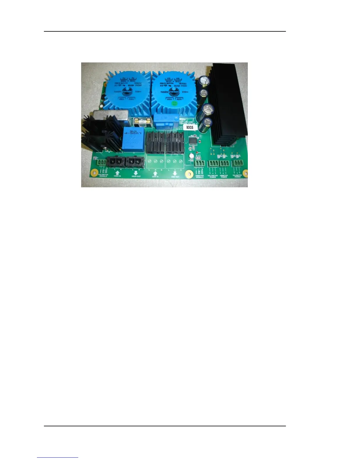
Figure 5: Topside Power Supply Board
Topside Power Supply PCB
Overview
The Topside Power Supply PCB provides the power needed by the Topside
Telemetry PCB, the High Voltage and Mains Current sensing circuits, and the
LCD displays. The Topside Power Supply Board is illustrated in Error!
Reference source not found.. The board contains the sensing circuits used
to measure the umbilical High Voltage and the Mains Input Current and
outputs these measurements for indication on the voltmeter and ammeter
displays.
Topside Power Supply Circuit Description
The Topside Power Supply Board has the following plug connections:
PL1 Supply input to the Current Sensing Circuit
PL2 Supply output from the Current Sensing Circuit
PL3 Supply input to the High Voltage Sensing Circuit
PL4 Supply Output from the High Voltage Sensing Circuit
PL5 Sensor output to Voltmeter Display
PL6 Sensor output to Ammeter Display
PL7 Voltmeter Display power
PL8 Ammeter Display power
PL9 Telemetry PCB Power
The supply input on PL1 passes through the current sensing circuit and is then
split to provide power to the power supply circuitry before passing to PL2.