Neptune 5000
© Copyright Datem Limited 2014
21
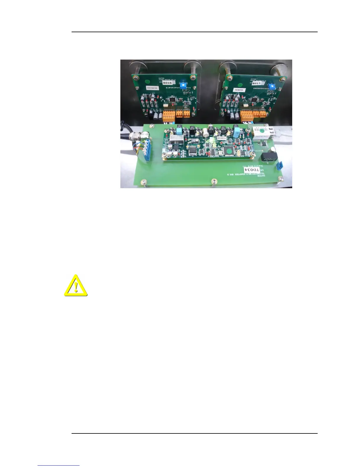
Figure 9: LCD Displays
Each display module has one input connector PL1 for DC Power and Signals
from the Topside Power Supply board.
Both the ammeter and voltmeter displays and the Topside Power Supply board
are factory calibrated to standard levels enabling any one item to be replaced
with a new item.
Maintenance
WARNING:
Appropriate safe working practices should be followed to ensure that all
hazards are minimised. It should be noted that although the power
switches may be turned off, there are still live terminals inside the box.
The electrical cables connected to the Topside control box should be visually
inspected regularly to ensure there are no chafes or cuts in the insulation. The
connectors on both ends of the cables should be tightly fitted with no face gap,
and the lock-rings should be finger-tight. Any damage to the mains power or
umbilical link cable insulation requires replacement of the cables. Damage to
the PC communication cable insulation can be repaired with the application of
adhesive lined shrink sleeve, providing the inner cores are not damaged.