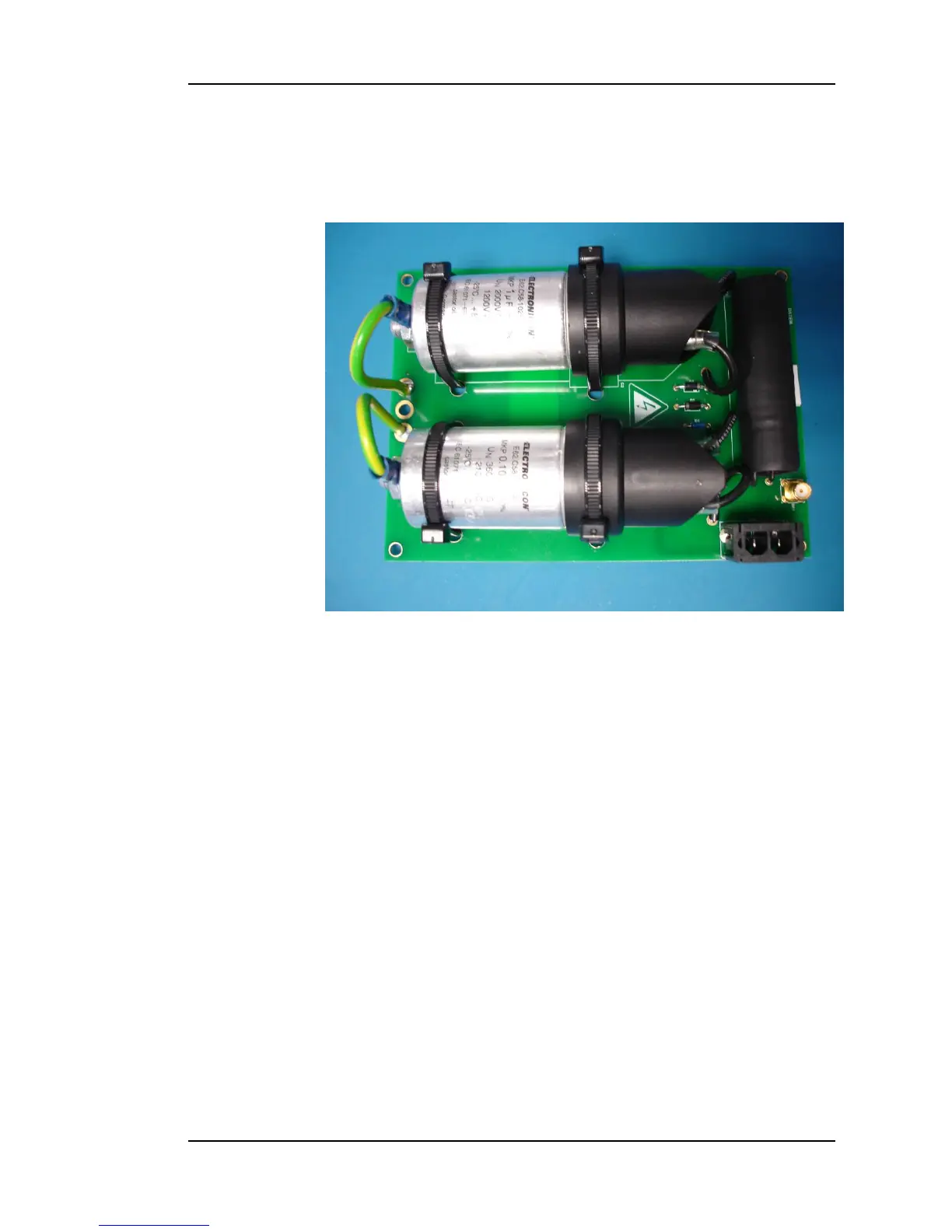
Figure 7: Data Coupler PCB
The Data Coupler PCB is used to superimpose Topside FSK data on to the high
voltage CPT supply and, conversely, to recover FSK data from the Subsea
Telemetry PCB. The high voltage supply is connected to the data coupling
board via J1. The data is passed to J2, the gold coax connector, which is in
turn connected to the telemetry board.
Since the voltage levels of the recovered FSK data are dependent on the
length of the umbilical cable, both telemetry boards carry out an automatic
“tuning” sequence during power-up, in order to set the recovery threshold
voltage. If, for example, power has been applied to the Topside Control Box
but not to the subsea CPT, the Topside Telemetry PCB will repeat its tuning
sequence until the Subsea Telemetry Board has been powered up. Once
communication has been established, each board continuously transmits a
“handshake” message while checking for received handshake messages. (This
process is independent of any communications between the Topside PC and
the Subsea Microcontroller.) A breakdown in telemetry communications,
indicated by a loss of handshake messages, immediately causes both boards
to repeat the tuning sequence.
LED Indicators
Seven LED indicators are fitted to the Topside Telemetry Board. Three green
LEDs show the power supply status: “+15V” and “-15V” are generated by the
Topside Power Board, while “+5V” is derived from the +15V supply by an on-
board voltage regulator. Four yellow LEDs monitor communications activity:
“Rx0” is illuminated whenever a character is received from the Topside PC;