98 Part Number GA_SM 08/18
Diagrams Section 9
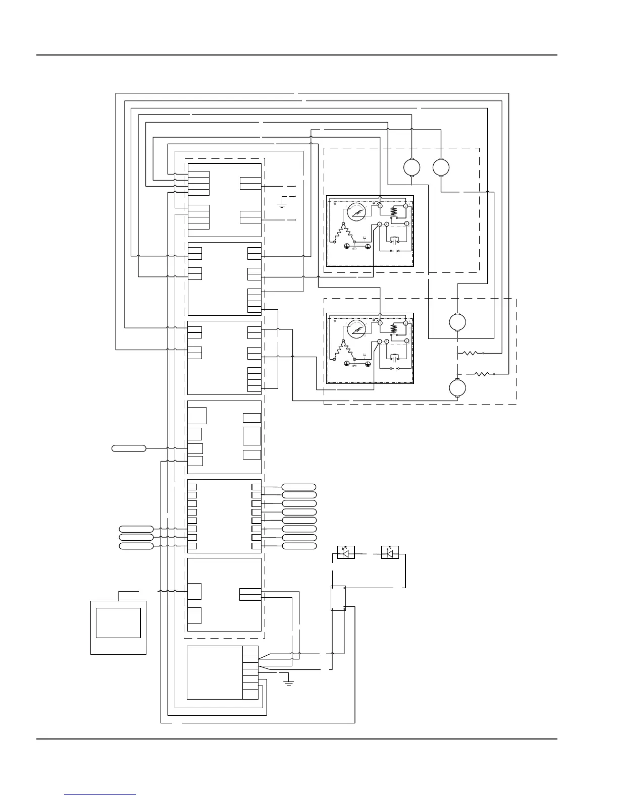
One Section Dual Temperature Wiring Diagram
Power Monitoring Shield (PWM)
Out
Neutral
Out
Line
In
Neutral
In
Common Control Board (CCB)
J2
Mod
Bus
J5 (+)
(-)
Solid State Shield 2 (SSR2)
TB201
TB201
TB201
TB201
TB101
TB101
TB102
TB102
Analog Temperature Shield
1
TB103
TB103
TB104
TB104
Solid State Shield 1 (SSR1)
TB201
TB201
TB201
TB201
TB101
TB101
TB102
TB102
TB103
TB103
TB104
TB104
2
3
4
5
6
7
8
16
15
14
13
12
11
10
9
J1
Mod
Bus
I/O Stack
1 secon
Dual Temp
Cond inlet probe
Cond outlet probe
Evap inlet probe
Evap outlet probe
Box temp probe
Ambient temp probe
L1
N
3
4
Power Supply
L(+)
+V
-V
GRN
N(-)
Output: 24VDC
Input: 85-264 VAC
5
6
G
G
10
M
Refg Compressor
9
Condenser
Fan
8
Frame
Heater
12
20
Black
Red
LED
Driver
5
1
12 13
24
Blue to
Black
LED
Light
Black
Red
User Interface
Cat 6 Cable
7
11
2
Freezer compressor
Yellow
To Red
Black
LED
Light
M
19
M
Condenser
Fan 2
M
Evaporator
Fan 2
Defrost
Heater
15
1
Evaporator
Fan
Refrigerator
13
14
17
16
Freezer
Humidity Sensor
Digital Input / Output Shield
101
201
302
403
402
401
301
Cond inlet probe (Frz)
Cond outlet probe(Frz)
Evap inlet probe (Frz)
Evap outlet probe (Frz)
Box temp probe (Frz)
Line
 Loading...