4. Open the latch and disconnect the camera cable from the connector (CAM1) on the system board.
5. Peel the tape that secures the display-cable connector latch to the system board.
6. Open the latch and disconnect the display cable from the connector (LCD1) on the system board.
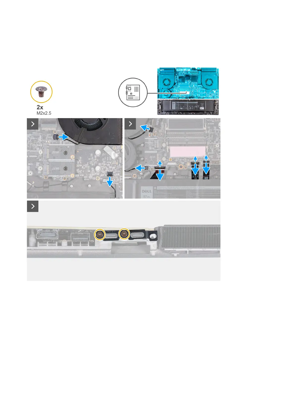
7. Disconnect the power-adapter port cable from the connector (DCIN1) on the system board.
8. Peel the power-adapter port cable from the system board.
9. Disconnect the right-fan cable from the connector (FAN2) on the system board.
10.Disconnect the speaker cable from the system board.
11. Disconnect the two left-fan cables from the connector (FAN1 and FAN4) on the system board.
12. Open the latch and disconnect the left I/O board cable from the connector on the system board.
13. Open the latch and disconnect the keyboard-controller board cable from the connector (KBBL2) on the system board.
14. Open the latch and disconnect the touchpad from the connector (TPAD1) on the system board.
15.Remove the two screws (M2x2.5) that secure the Type-C bracket to the system board.
77