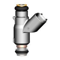
Multec 3.5 Fuel Injector Application Manual Fundamentals
Delphi Energy and Chassis Systems
Revision: 11/05-1 2-27
2.4.4 Impact of EGR and PCV on engine fueling
As with canister purge, EGR (exhaust gas recirculation) and PCV
(positive crankcase ventilation) can affect the amount of fuel required
during a given cycle. The method of compensating for EGR and PCV is
not identical to canister purge, however, and methods of compensating
must be considered separately from canister purge.
EGR has the impact of displacing fresh air in the intake manifold,
reducing the fuel requirement for a given set of engine speed and load
conditions. EGR is considered an inert gas (consisting mostly of
combustion products and water vapor), and does not burn when added to
the combustion process. The effect of EGR can typically be compensated
for by measuring actual intake airflow (if a mass airflow meter is used) or
via the change in manifold pressure caused by the EGR.
While PCV contains some fuel vapor (similar to canister purge), it also
contains a large amount of water vapor. While the water vapor is inert
(like EGR), the fuel vapor can be combusted and thus must be
compensated for in a manner similar to canister purge.
2.4.5 Injector Flow Characterization
Refer to Fuel Rail
Applications Manual
Once the correct fuel injector (including fuel rail assembly) and fuel pump
supply systems are determined, flow data used for characterizing injector
performance can be generated. Flow characterization requirements will
depend on the type of fuel system (for example, vacuum biased
recirculating or returnless) and the sophistication of the engine controller
software package. Typically, the complexity of the data required for the
fuel system calibration is dependent on the emissions requirements. Some
of the more important fuel system calibration parameters, as well as a
suggestions for obtaining the most relevant data, are listed below:
Delphi suggests collecting fuel calibration data with the entire fuel system
– fuel rail conduits, fuel injectors and fuel pressure regulator. This will
allow the fuel calibration to compensate for fuel distribution variation and
fuel pressure regulator gain.
Injector Slope & Intercept Injector slope and intercept of pulse width vs flow rate will form
the base fuel flow curve. Typically, this base fuel flow curve is a
linear regression of the data collected.

 Loading...