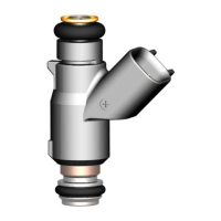
Multec 3.5 Fuel Injector Application Manual Product Description
Delphi Energy and Chassis Systems
Revision: 11/05-1 3-35
When using gaseous leak check techniques (bubble, pressure decay, or
mass flow), it is imperative to perform an injector internal drying
procedure by cycling the injector with pressurized clean dry air prior to
leak test. All liquid must be cleared from the valve area in order to obtain
a valid leak rate. The presence of liquid, which is an order of magnitude
more viscous than a gas, may produce a false low leakage measurement.
To obtain accurate injector tip leakage measurements, adequate time must
be allowed for the injector to cool following the purge procedure prior to
performing the leak test.
Note
Injector leak is normally the last functional test performed during injector
manufacturing. Therefore the injectors are delivered to the customer in
the dry state. If a functional gaseous leak test is to be performed on the
injector, rail or fuel system prior to introducing fuel into the system, the
injector may produce a false leak. This may be due to the injector valve
becoming unseated in the dry state during shipping and handling. If this
occurs, a momentary pulse of the fuel injector is recommended to reseat
the valve and correct the false leak. (See section 6 – Product Handling.)
Note
While changes in tip leakage could effect crank times, evaporative
emissions and exhaust emissions, it is important to properly diagnose
such problems as tip leakage may not be a factor. Other possible causes
include a malfunctioning pump check valve, regulator leakage, etc.
3.11.1 Total Fuel System Tip Leakage Monte Carlo Analysis
At a vehicle level the total tip leakage from all the injectors in a fuel
system is of more significance than the individual injector tip leak rates.
A portion of the total vehicle evaporative HC emissions can be allocated
to fuel system injector tip leakage.
Rather than specify a stringent maximum leak rate for each injector to
ensure an assembly made up of worst case specification limit tip leak
injectors does not exceed the fuel system limits, a Monte Carlo analysis
of total fuel system leakage can be performed. The Monte Carlo analysis
determines the cumulative percentage of rail assemblies vs total leak for a
given distribution of injector tip leakages.
For example, if maximum total fuel system tip leak for a 4 cylinder rail is
specified at 1.6 cc/min, an injector maximum tip leakage specification of
0.40 cc/min could be used to guarantee all fuel systems meet the 1.6
cc/min specification. Alternatively, the distribution of tip leak rates from
a production lot of injectors can be used in a Monte Carlo analysis to
simulate 5000 rail builds and determine the total tip leak distribution.
The total tip leakage for the rail is determined by selecting 4 injectors at
random from the production injector tip leak distribution and adding the
tip leakages. The cumulative percentage of rails with a total tip leak rate
less than the specified value is calculated. Typically a compliance level
is specified for the total rail tip leak that allows a very small percentage

 Loading...