Multec 3.5 Fuel Injector Application Manual Product Description
Delphi Energy and Chassis Systems
Revision: 11/05-1 3-9
The fuel injector meters fuel to the engine based on the duration of the
voltage signal received from the engine controller drive circuit. During
each cylinder cycle the injector receives a voltage signal energizing the
coil and creating a magnetic field. The magnetic field lifts the armature
valve off the seal seat allowing fuel to flow to the director plate. When
the voltage is terminated, the magnetic field diminishes and the valve
spring returns the armature valve to the closed position ending fuel flow.
See Figure 3-7.
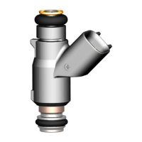
Pressurized fuel enters the injector at the top via its connection to the fuel
rail. The fuel passes through the center of the injector. A filter at the
injector inlet protects the injector valve from particulate contamination
present in the fuel system between the chassis filter and the injector. (The
chassis filter is intended as the primary filtration point in the fuel system.
The injector internal filter is non-serviceable.) The fuel passes through the
center of the armature valve, then radially outward through cross drillings
before it reaches the seat seal area. When the armature valve lifts (less
than 0.10 mm) fuel is allowed to flow past the valve and seat to the
director plate which meters the flow rate and generates the spray pattern
via the size, number and orientation of holes. See Figure 3-8.