ASDA-A2 Chapter 3 Wiring
Revision February, 2017 3-55
The definition of each signal is as follows:
Drive Connector Encoder Connector
PIN No.
Terminal
Symbol
Function and Description
Military
Connector
Quick
Connector
Color
5 T+
Serial communication signal
input / output (+)
A 1 Blue
4 T-
Serial communication signal
input / output (-)
B 4 Blue & Black
14,16 +5V +5V power supply S 7
Red / Red &
White
13,15 GND Power ground R 8
Black / Black
& White
Shell Shielding- Shielding L 9 -
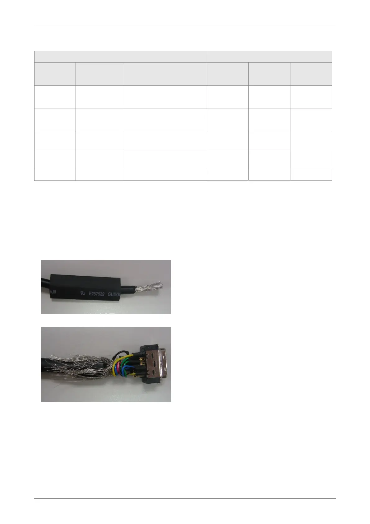
About shielding and ground
The both sides of CN2 encoder cable are CN2 connector and encoder connector. Shielding and
ground conductor should be correctly connected to the corresponding pins so as to effectively
shield and ground.
The shielding procedures of CN2 encoder connector are as followings:
(1) Cut through the cable and expose the core
wire which covers the metal core wires with
shielding. The reserved core wire length
should be 20~30mm. Then, cover a 45mm
heat shrink tube on the cable.
(2) Spread the metal core wires with shielding
and turn it upside down in downward
direction. Ensure to follow the above table of
CN2 Terminal Signal Identification to connect
the pins one by one.

 Loading...


