EasyManua.ls Logo

Delta ASDA-B2-F Series User Manual

Delta ASDA-B2-F Series
291 pages
To Next Page IconTo Next Page
To Previous Page IconTo Previous Page
Page #189 background imageLoading...
Page #189 background image
Communications ASDA-B2-F
8-4 September, 2015
8
8.3 MODBUS Communication Protocol
There are two modes of MODBUS network communication: ASCII (American Standard Code for
Information Interchange) and RTU (Remote Terminal Unit). Users could set the desired
communication mode via P3-02. Apart from these two communication modes, this servo drive
also supports functions of accessing more than one data (03H), writing one character (06H) and
writing multiple characters (10H). Please refer to the following descriptions.
Code Description
ASCII Mode:
In ASCII mode, data are transmitted in ASCII (American Standard Code for Information
Interchange) format. When transmitting data 64H between two stations (Master and Slave), the
master will send 36H to represent 6” and 34H to represent “4”.
ASCII code for digits 0 to 9 and characters A to F are as follows:
Character ‘0’ ‘1’ ‘2’ ‘3’ ‘4’ ‘5’ ‘6’ ‘7’
ASCII Code 30H 31H 32H 33H 34H 35H 36H 37H
Character ‘8’ ‘9’ ‘A ‘B’ ‘C’ ‘D’ ‘E’ ‘F’
ASCII Code 38H 39H 41H 42H 43H 44H 45H 46H
RTU Mode:
Every 8-bit data is constituted by two 4-bit characters (hexadecimal). If data 64H is transmitted
between two stations, it will be transmitted directly, which is more efficient than ASCII mode.
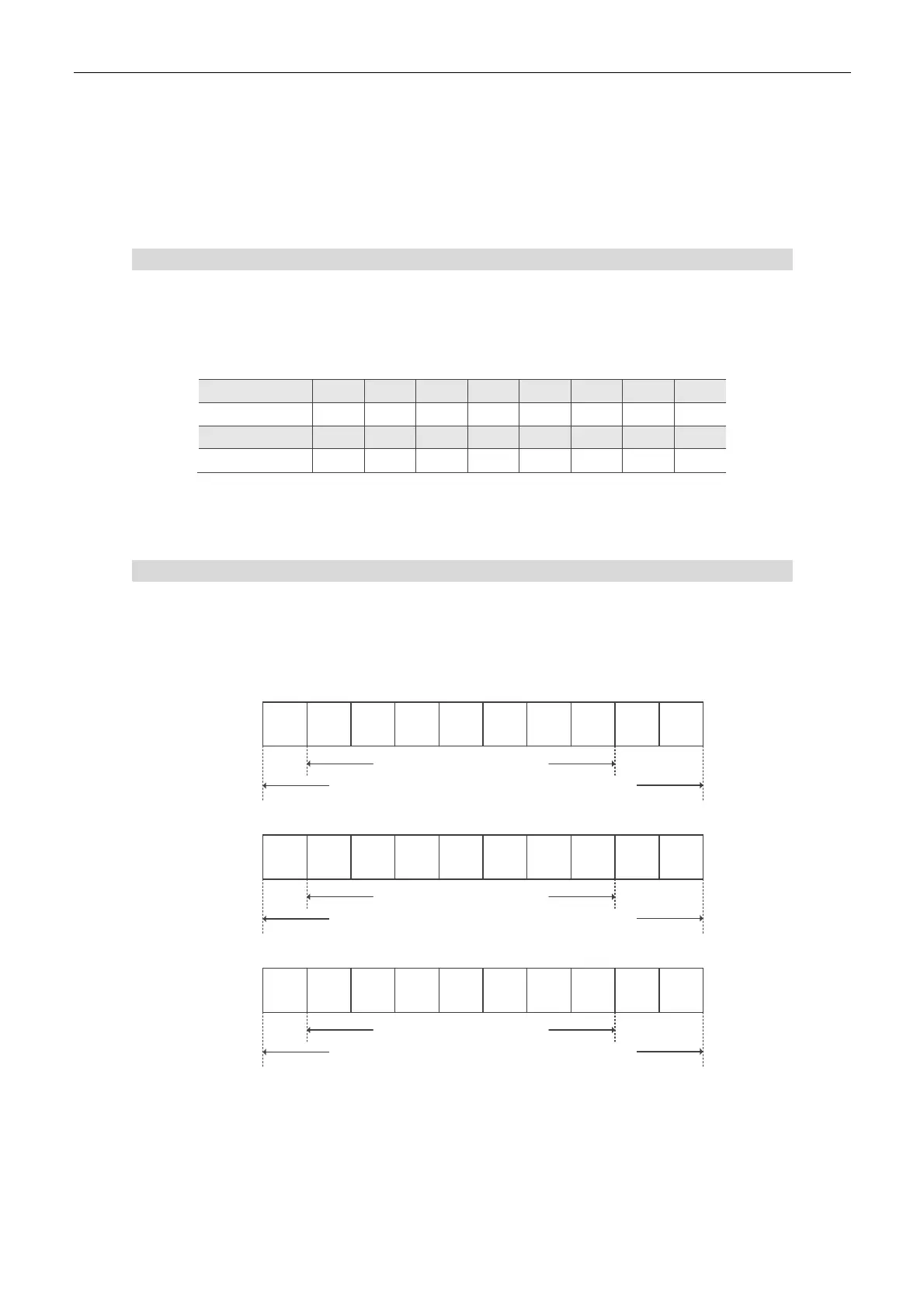
Character Structure
Characters will be encoded into the following framing and transmitted in serial. The checking
method of different bit is as the following.
10-bit character frame (for 7-bit character)
7N2
Start
bit
Stop
bit
Stop
bit
0123456
7-data bits
10-bit character frame
LHH
7E1
Start
bit
Even
Parity
Stop
bit
0123456
7-data bits
10-bit character frame
LH
7O1
Start
bit
Odd
Parity
Stop
bit
0123456
7-data bits
10-bit character frame
LH

Table of Contents

Questions and Answers:

Delta ASDA-B2-F Series Specifications

General IconGeneral
ModelASDA-B2-F Series
Power Range0.1kW to 3kW
Control ModesPosition, Speed, Torque
Protection ClassIP20
TypeServo Drives
Communication InterfaceRS-485, CANopen
Feedback Resolution17-bit
Protection FeaturesOvervoltage, Undervoltage, Overcurrent
Operating Temperature0°C to 55°C
Storage Temperature-20°C to 65°C
CertificationsCE, UL
Input Voltage200VAC ~ 230VAC, Single/Three Phase; 100VAC ~ 120VAC, Single Phase (Specific models)
Humidity90% RH or less (non-condensing)

Summary

Preface

Inspection and Model Explanation

1.1 Inspection

Procedure to check the servo drive and motor for damage and correctness before operation.

1.2 Product Model

Details on understanding the nameplate information for servo drives and motors.

1.3 Servo Drive and Corresponding Servo Motor

Table matching servo drive models with their corresponding servo motors for proper system configuration.

1.4 Each Part of the Servo Drive

Identification and description of the various parts and terminals of the servo drive unit.

Installation

2.1 Notes

Key points and precautions to observe during installation for proper operation and to prevent damage.

2.3 Ambient Conditions of Installation

Specifies the recommended environmental conditions for installing the servo drive.

2.4 Installation Direction and Space

Guidelines on mounting orientation and required clearance for optimal cooling and ventilation.

2.6 EMI Filter Selection

Guidance on selecting appropriate EMI filters based on servo drive models and power.

2.7 Selection of Regenerative Resistor

Information on selecting built-in and external regenerative resistors based on servo drive specifications.

Wiring

3.1.1 Connecting to Peripheral Devices

Diagrams and instructions for connecting external devices like power, contactors, and controllers.

3.1.2 Connectors and Terminals of Servo Drive

Detailed explanation of the terminal signals and connectors on the servo drive unit.

3.2 Basic Wiring

Illustrates basic wiring diagrams for different servo drive models and power configurations.

3.3 I / O Signal (CN1) Connection

Details on the I/O signal connector, including terminal layout and signal explanations.

3.6 CN6 Connector (DMCNET)

Information on the DMCNET communication connector, its pin assignments, and function.

Panel Display and Operation

4.1 Panel Description

Overview of the servo drive's front panel, including displays and key functions.

4.2 Parameter Setting Procedure

Step-by-step guide on how to navigate and change parameters using the control panel.

4.3 Status Display

Explanation of various status displays, including save status, decimal points, and alarm messages.

4.4.2 JOG Mode

Procedure for operating the servo motor in JOG mode for testing and setup.

Trial Operation and Tuning

5.1 Inspection without Load

Procedures for inspecting the servo motor and drive without load to ensure safety and proper function.

5.2 Apply Power to the Servo Drive

Instructions for applying power to the servo drive and checking initial status displays and warnings.

5.3 JOG Trial Run without Load

Procedure for performing a basic test run of the motor using JOG mode without any load.

5.5 Tuning Procedure

Detailed steps for estimating inertia ratio and performing auto or semi-auto tuning.

5.5.3 Flowchart of Auto Tuning

Step-by-step flowchart illustrating the process of auto tuning the servo system.

5.5.6 Mechanical Resonance Suppression Method

Methods to suppress mechanical resonance using Notch filters and manual adjustments.

Control Mode of Operation

6.1 Selection of Operation Mode

Overview of the three basic operation modes: Position, Speed, and Torque, and how to select them.

6.2 Position Mode

Details on using the servo drive in position mode, including control structure and command processing.

6.3 Speed Mode

Explanation of speed control mode, including command selection, structure, and filters.

6.3.6 Resonance Suppression

Methods and parameters for suppressing resonance in the servo system.

6.4 Torque Mode

Description of torque control mode, including command selection and control structure.

6.5 The Use of Brake

Guidance on the operation and timing of the motor brake controlled by the servo drive.

Parameters

7.1 Parameter Definition

Explanation of parameter groups, naming conventions, and special symbol descriptions.

7.2 List of Parameters

A detailed list of all parameters, their functions, default values, and control mode compatibility.

P0-xx Monitor Parameters

Description of monitor parameters used for observing servo drive status and variables.

P1-xx Basic Parameters

Details on fundamental parameters for configuring servo drive operation and limits.

P2-xx Extension Parameters

Configuration parameters for advanced functions like loop gains, filters, and suppression.

P3-xx Communication Parameters

Parameters for setting up serial communication protocols, speed, and addresses.

P4-xx Diagnosis Parameters

Parameters related to diagnosing servo drive status, faults, and digital I/O.

P5-xx Motion Setting Parameters

Parameters for configuring motion control aspects like acceleration, deceleration, and software limits.

Communications

8.1 RS-232 Communication Hardware Interface

Details on the hardware interface and wiring for RS-232 serial communication.

8.2 RS-232 Communication Parameters Setting

Configuration of essential RS-232 communication parameters like address, speed, and protocol.

8.3 MODBUS Communication Protocol

Explanation of MODBUS communication modes (ASCII, RTU), character structure, and data frames.

8.4 Setting and Accessing Communication Parameters

Information on setting and accessing parameters via communication for various groups.

Troubleshooting

9.1 Alarm of Servo Drive

List and description of servo drive alarms, their corresponding DO signals, and servo status.

9.2 Alarm of DMCNET Communication

Details on alarms related to DMCNET communication errors and status.

9.3 Alarm of Motion Control

List of alarms specific to motion control functions and their corrective actions.

9.4 Causes and Corrective Actions

Troubleshooting guide listing common causes for alarms and recommended corrective actions.

Absolute System

10.1 Absolute Type of Battery Box and Wiring Rods

Specifications, precautions, and dimensions related to battery boxes and wiring for absolute encoders.

10.2 Installation

Instructions for installing the battery box and connecting it to the servo drive and motor.

10.3 Parameters Related to Absolute Servo System

List of parameters that are relevant to the absolute servo system configuration and operation.

10.5 System Initialization and Operation Procedures

Procedures for system initialization, accessing absolute position, and handling coordinate systems.

Appendix A: Specifications

Specifications of ASDA-B2-F Servo Drive

Detailed electrical and mechanical specifications for the ASDA-B2-F servo drive series.

Specifications of Servo Motors (ECMA Series)

Comprehensive specifications for ECMA series servo motors, including performance and dimensions.

Torque Features (T-N Curves)

Torque-speed (T-N) curves illustrating the performance characteristics of ECMA series servo motors.

Overload Features

Information on overload protection mechanisms and graphs showing load vs. operating time.

Dimensions of Servo Drive

Dimensional drawings and specifications for various ASDA-B2-F servo drive models.

Dimensions of Servo Motor

Dimensional drawings and specifications for ECMA series servo motors of different frame sizes.

Appendix B: Accessories

Power Connector

Details and part numbers for various power connectors used with the servo system.

Power Cable

Specifications and part numbers for different power cables, including lengths and connector types.

Encoder Connector

Details on encoder connectors, including part numbers and pin configurations.

Encoder Cable (Absolute Type)

Part numbers and specifications for connection cables designed for absolute encoders.

Battery Box Cable AW

Dimensional diagrams and part numbers for Battery Box Cable AW.

Battery Box (Absolute Type)

Dimensions and part numbers for single and dual battery boxes used with absolute encoders.

PC Connection Cable

Details on the PC connection cable used for software communication and setup.

Optional Accessories

List of optional accessories available for ASDA-B2-F series servo drives and motors.

Appendix C: Maintenance and Inspection

Basic Inspection

Routine checks for the servo drive and motor, including tightening screws and cleaning.

Maintenance

Guidelines for proper product storage, cleaning ventilation ports, and general maintenance practices.

The Lifetime of Machinery Parts

Information on the expected lifetime of key components like DC bus capacitors, relays, and cooling fans.

Revision History

Related product manuals