Chapter 8 Option CardsC2000
8-39
Environment
Noise immunity
ESD (IEC 61800-5-1, IEC 61000-4-2)
EFT (IEC 61800-5-1, IEC 61000-4-4)
Surge Test (IEC 61800-5-1, IEC 61000-4-5)
Conducted Susceptibility Test (IEC 61800-5-1, IEC 61000-4-6)
Operation
-10°C
–15°C (temperature), 90% (humidity)
Storage
-25°C
–70°C (temperature), 95% (humidity)
Vibration / shock
immunity
International standard: IEC 61800-5-1, IEC 60068-2-6 / IEC 61800-5-1,
IEC 60068-2-27
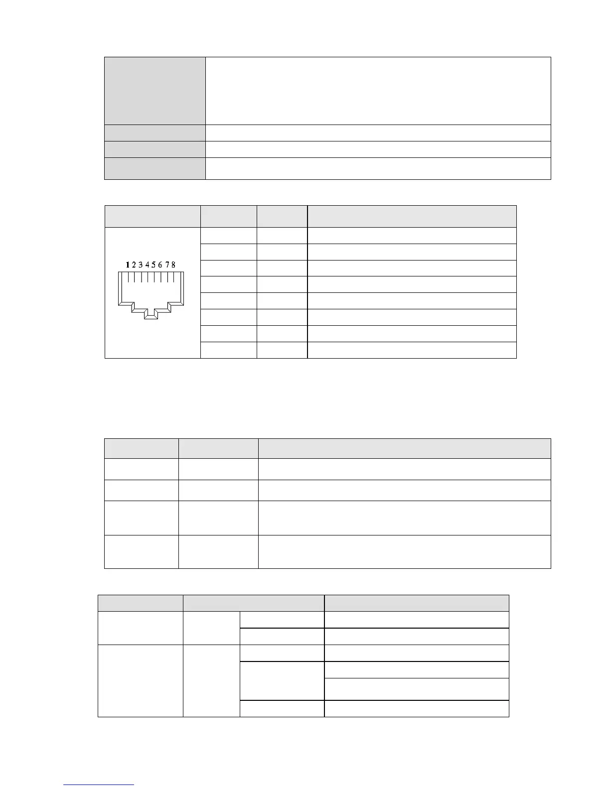
8-15-4 RJ-45 PIN Definition
RJ-45 PIN No. Signal Definition
1 Tx+ Positive pole for data transmission
2 Tx- Negative pole for data transmission
3 Rx+ Positive pole for data receiving
4 -- N / C
5 -- N / C
6 Rx- Negative pole for data receiving
7 -- N / C
8 -- N / C
8-15-5 Communication Parameters for VFD-C2000 Connected to EtherCAT
When operating VFD-C2000 via CMC-EC01, please set the control and operation command as
controlled by communication card. When C2000 is connected to EtherCAT network, please set up
the communication parameters according to the table below.
8-15-6 LED Indicator
LED Status Indication
POWER Green
On Power supply in normal status
Off No power supply
LINK Green
On Operate in normal status
Flashes
Pre-operation (On / Off 200ms)
Operate in safe mode
(On 200ms / Off 1000ms)
Off Initial state
Parameter Set value (Dec) Explanation
Pr. 00-20 8
The frequency command is controlled by communication card.
Pr. 00-21 5 The operation command is controlled by communication card.
Pr. 09-60 6
Identification: when CMC-EC01 is connected, Pr.09-60 will show
value 6 (EtherCAT Slave)
Pr. 09-61 --
Version of communication card
 Loading...


