Chapter 12 Description of Parameter SettingsC2000
12.1-00-11
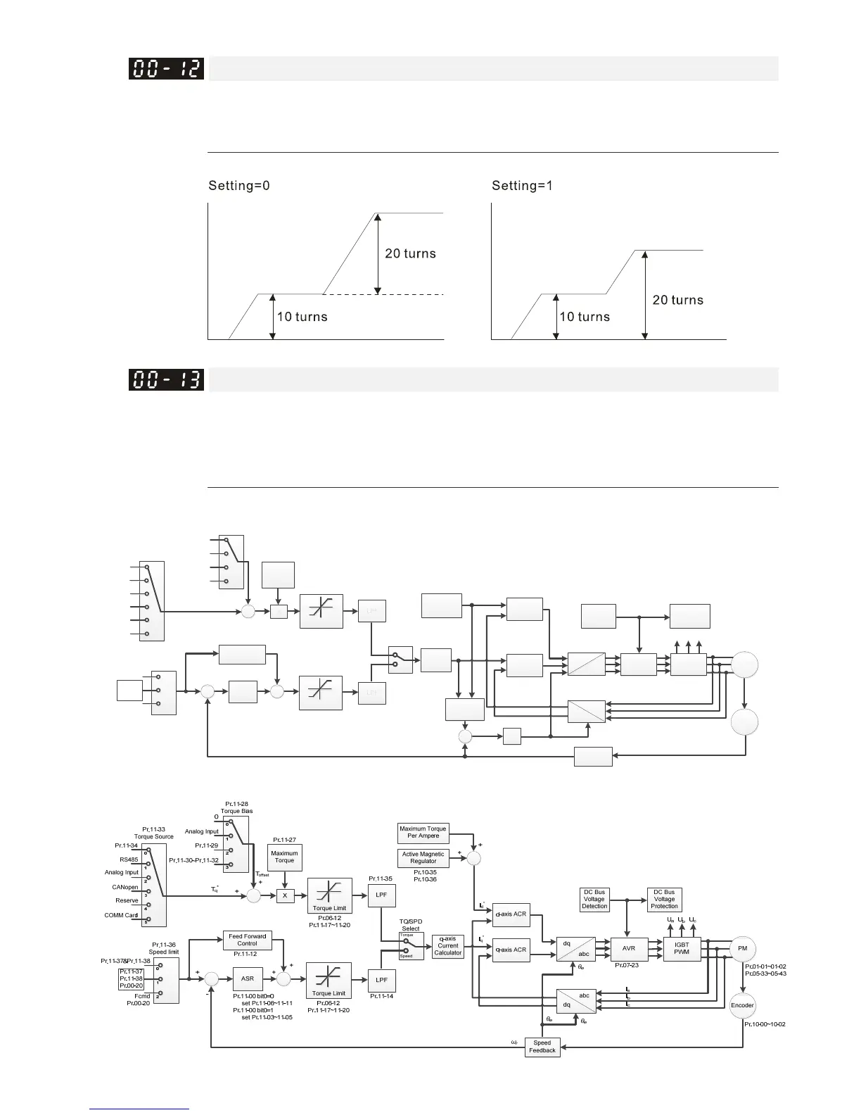
Point-to-Point Position Control
Default: 0
Settings: 0: Relative position
1: Absolute position
Pr. 00-12 = 0 is incremental type P2P; Pr. 00-12 = 1 is absolute type P2P
Control of Torque Mode
Default: 0
Settings
0: IM TQCPG (IM Torque control + Encoder)
1: PM TQCPG (PM Torque control + Encoder)
2: IM TQC Sensorless (IM Sensorless torque control)
Pr. 00-13=0, IM TQCPG control diagram is as follows:
IGBT
PWM
dq
abc
q-axis ACR
Speed
Feedback
θ
e
ω
r
Pr.01-01~01-02
Pr.05-01~05-09
Slip Calculator
+
ω
sl
ʃ
+
AVR
Pr.07-23
Encoder
Pr.10-00~10-02
dq
abc
U
a
U
b
U
c
I
q
*
IM
DC Bus
Voltage
Detection
DC Bus
Voltage
Protection
DC Bus Voltage
I
a
I
b
I
c
Active
Magnetic
Regulator
d-axis ACR
Pr.11-21
Pr.11-22
Pr.10-35
Pr.10-36
I
d
*
Torque
Speed
TQ/SPD
Select
LPF
Pr.11-35
LPF
Pr.11-14
Torque Limit
ASR
-
+
Feed Forward
Control
Pr.11-12
0
Pr.11-33
Torque Source
Pr.11-34
3
4
5
RS485
Analog Input
1
2
CANopen
Reserve
COMM Card
+
Maximum
Torque
X
Pr.11-27
Torque Limit
Pr.06-12
Pr.11-17~11-20
Pr.06-12
Pr.11-17~11-20
++
Pr.11-00 bit0=0
set Pr.11-06~11-11
Pr.11-00 bit0=1
set Pr.11-03~11-05
+
Pr.11-28
Torque Bias
0
Pr.11-29
Analog Input
Pr.11-30~Pr.11-32
0
1
2
3
0
1
Pr.11-36
Speed limit
Pr.11-37&Pr.11-38
2
Pr.11-37
Pr.11-38
Pr.00-20
Fcmd
Pr.00-20
T
offset
T
q
*
q-axis
Current
Calculator
Pr. 00-13=1, PM TQCPG control diagram is as follows:
 Loading...


