Chapter 12 Description of Parameter SettingsC2000
12.1-02-13
65: Output for CANopen and RS-485
66: SO output logic A
67: Analog input signal level reached
68: SO output logic B
70: FAN warning detection output
Use this parameter to set the function of the multi-function terminals.
Pr. 02-36~Pr. 02-41 requires additional extension cards to display the parameters, the choices of
optional cards are EMC-D42A and EMC-R6AA.
The optional card EMC-D42A provides 2 output terminals and can be used with Pr. 02-36~02-37.
The optional card EMC-R6AA provides 6 output terminals and can be used with Pr. 02-36~02-41.
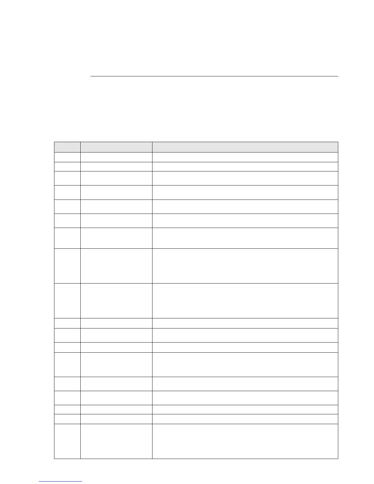
Summary of function settings
Take the normally open contact (N.O.) for example, ON: contact is closed, OFF: contact is open
Settings Functions Descriptions
0 No Function Output terminal with no function
1 Indication during RUN Active when the drive is not in STOP.
2
Operation speed
reached
ctive when output frequency of the drive reaches the setting
frequency.
3
Desired Frequency
reached 1 (Pr. 02-22)
Active when the desired frequency (Pr. 02-22) is reached
4
Desired Frequency
reached 2 (Pr. 02-24)
Active when the desired frequency (Pr. 02-24) is reached.
5
Zero Speed (
ctive when frequency command =0. (the drive must be at RUN
status)
6
zero speed including
STOP (Frequency
command)
Active when frequency command =0 or stopped.
7 Over-torque 1
Active when the drive detects over-torque. Pr.06-07 sets the
over-torque detection level (motor 1), and Pr.06-08 sets the
over-torque detection time (motor 1).
Refer to Pr.06-06–06-08.
8 Over-torque 2
Active when the drive detects over-torque. Pr.06-10 sets the
over-torque detection level (motor 2), and Pr.06-11 sets the
over-torque detection time (motor 2).
Refer to Pr.06-09–06-11.
9 Drive is Ready Active when the drive is ON and with no error detected.
10 Low voltage warning (Lv)
ctive when the DC BUS voltage is too low. (refer to Pr. 06-00 low
voltage level)
11 Malfunction Indication Active when fault occurs (except Lv stop).
12
Mechanical Brake
Release (Pr. 02-32)
When drive runs after Pr. 02-32, it will be ON. This function should
be used with DC brake and it is recommended to use contact “b”
(N.C.).
13 Over-heat warning
ctive when IGBT or heat sink overheats; to prevent the drive
from shutting down due to over-heating (refer to Pr.06-15).
14
Software Brake Signal
Indication
Active when the soft brake function is ON. (refer to Pr. 07-00)
15 PID Feedback Error Active when the PID feedback signal error is detected.
16 Slip Error (oSL) Active when the slip error is detected.
17
Count value reached,
does not return to 0 (Pr.
02-20)
When the drive executes external counter, this contact is active if
the count value is equal to the setting value for Pr.02-20.
This contact is not active when the setting value for Pr.02-20 >
Pr.02-19.
 Loading...


