6 Installation
Installation and Operation Manual for RPI M6A M8A M10A inverters V1.0 2016-02-03
40
Data format
Baud rate 9600, 19200, 38400; Standard: 19200
Data bits 8
Stop bit 1
Parity not applicable
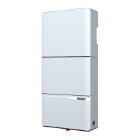
Dip switch for RS485 termination resistor
Fig. 6.26: DIP switch for RS485 termination resistor
Connecting to a Delta SOLIVIA Gateway M1 G2
On the inverter you connect individual wires, on the gateway you
have to use a RJ45 plug.
Connect the pins according to the following table:
Inverter SOLIVIA Gateway M1 G2
DATA+ Terminal 3 or 5 Pin 7
DATA– Terminal 4 or 6 Pin 6 or 8
6.3 RS485
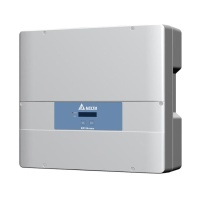
Terminal block for
RS485 and VCC
DIP switch for RS485
termination resistor
Terminal block for
RS485 and VCC
DIP switch for RS485
termination resistor
Fig. 6.24: Components on the RS485 card
RS485 is used to connect the inverters of the PV plant via a data-
logger to a monitoring system.
For connecting RS485, terminals 3/4 or 5/6 are used. It does not
matter which pair of terminals you use. The second pair you only
need when you connect multiple inverters via RS485.
If you want to use SOLIVIA Monitor, the Internet based monitor-
ing from Delta, you will also need a SOLIVIA M1 G2 Gateway.
Default baud rate is 19200 which can be changed on the inverter
(see chapter “8.5 Baud rate for RS485”, p. 69).
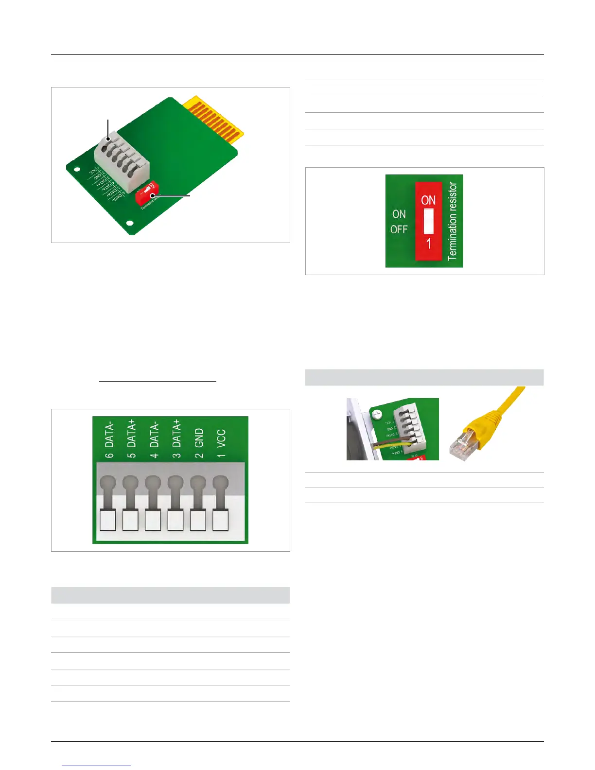
Pin assignment
Fig. 6.25: Pin assignment of RS485 terminal block
Pin Designation
1 VCC (+12 V; 0.5 A)
2 GND
3 DATA+ (RS485)
4 DATA– (RS485)
5 DATA+ (RS485)
6 DATA– (RS485)

 Loading...