VFD-V Series
DELTA ELECTRONICS, INC. ALL RIGHTS RESERVED
8-4
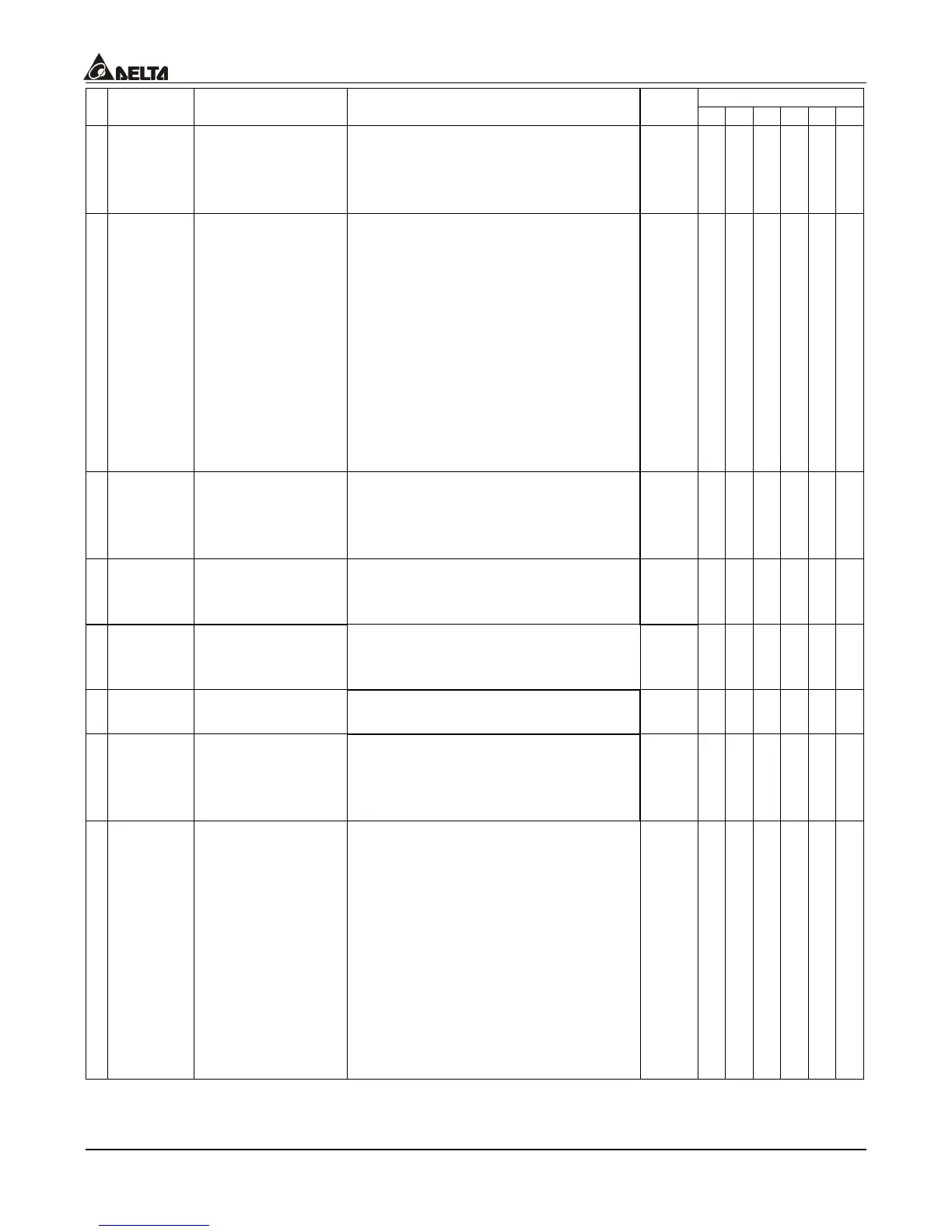
Control Mode
Parameters Functions Settings
Factory
Setting
VF VG SV SG T TG
a
00-12
Constant Torque
Operation
Selection
0: OL (100%) constant torque
operation
1: OL (125%) variable torque
operation
0
{ { { { { {
a
00-13
Optimal
Acceleration
/Deceleration
Setting
0: Linear acceleration/deceleration
1: Auto acceleration, linear
deceleration
2: Linear acceleration, auto
deceleration
3: Auto acceleration/deceleration
4: Linear
acceleration/deceleration, but
conduct the stall prevention
throughout the auto
acceleration/deceleration
function.
0
{ { { { ° °
00-14
Time Unit for
Acceleration
/Deceleration and
S Curve
0: unit: 0.01 sec
1: unit: 0.1 sec
0
{ { { { { {
a
00-15
Carrier
Frequency Upper
Bound
0: soft pwm
1~15KHz
10
{ { { { { {
a
00-16
Carrier
Frequency Lower
Bound
1-15KHz (disabled during soft
PWM)
10
{ { { { { {
a
00-17
Center Frequency
of Soft pwm
1~7KHz
3
{ { { { { {
a
00-18
Auto Voltage
Regulation (AVR)
Function
0: AVR function enabled
1: AVR function disabled
2: AVR function disabled during
deceleration
0
{ { ° ° ° °
a
00-19
Automatic
Energy-Saving
Operation
BIT0=0: Disable automatic
energy-saving operation
BIT0=1: Enable automatic
energy-saving operation
BIT1=0: Maximum output voltage
equals to the input power
voltage
BIT1=1: Maximum output voltage
could be greater than the
input power voltage
(over-modulation
available)
00010
{ { { { { {

 Loading...

