VFD-V Series
DELTA ELECTRONICS, INC. ALL RIGHTS RESERVED
8-28
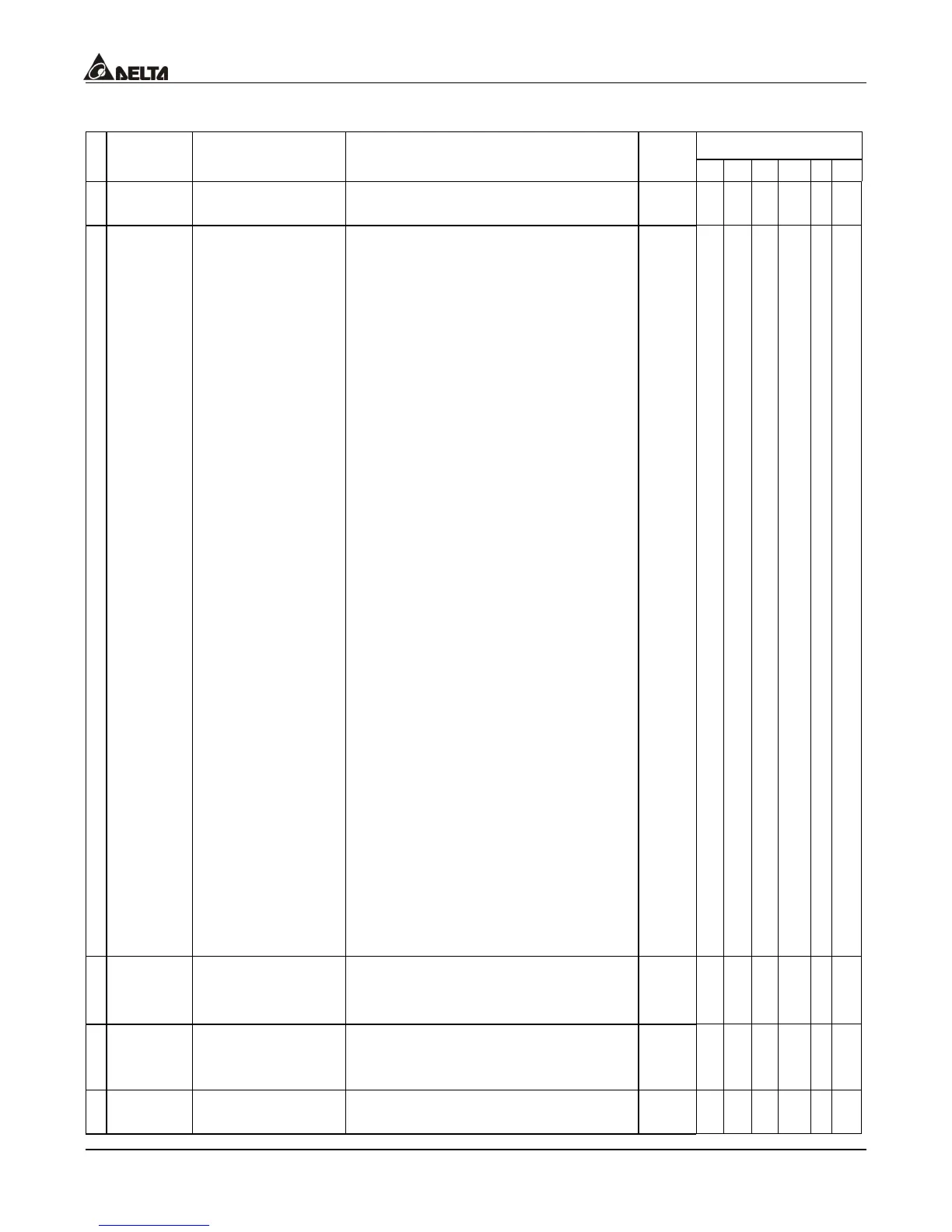
Group 10: Speed Feedback Parameter
Control Mode
Parameters Functions Settings
Factory
Setting
VF VG SV SG T TG
10-00
PG (encoder)
Pulses
1~20000 600
° { ° { ° {
10-01
Encoder Input
Setting (channel
1)
0: Phase A leads in a forward run
command and phase B leads in
a reverse run command.
(rising/falling edge trigger)
(Pulses x 4)
1: Phase B leads in a forward run
command and phase A leads in
a reverse run command.
(rising/falling edge trigger)
(Pulses x 4)
2: Phase A is a pulse input and
phase B is a direction input.
(low input = reverse direction,
high input = forward direction)
3: Phase A is a pulse input and
phase B is a direction input.
(low input = forward direction,
high input = reverse direction)
4: Phase A is a forward run pulse,
then phase B is High.
Phase B is a reverse run pulse,
then phase A is High.
5: Phase B is a forward run pulse,
then phase A is High.
Phase A is a reverse run pulse,
then phase B is High.
6: Phase A leads in a forward run
command and phase B leads in
a reverse run command. (level
trigger)
7: Phase B leads in a forward run
command and phase A leads in
a reverse run command. (level
trigger)
0
° { ° { ° {
a
10-02
PG Feedback
Fault Treatment
0: warn and keep operating
1: warn and RAMP to stop
2: warn and COAST to stop
0
° { ° { ° {
a
10-03
PG Feedback
Fault Detection
Time
0.00~10.00 Sec 0.10
° { ° { ° {
a
10-04
PG Feedback
Filter Time
0.001~1.000 Sec 0.003
° { ° { ° {

 Loading...

