VFD-V Series
DELTA ELECTRONICS, INC. ALL RIGHTS RESERVED
8-8
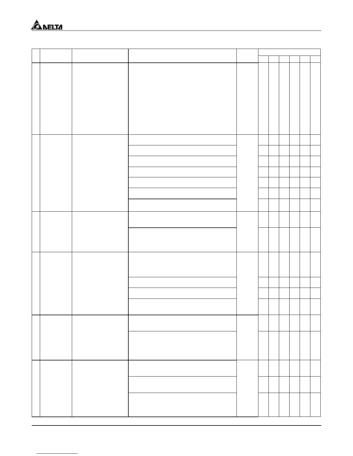
Group 2: Digital Output/Input Parameter
Control Mode
Parameters Functions Settings
Factory
Setting
VF VG SV SG T TG
02-00
2-Wire/3-Wire
Operation
Control
0: FWD/STOP, REV/STOP
1: FWD/STOP, REV/STOP (Line
Start Lockout)
2: RUN/STOP, REV/FWD
3: RUN/STOP, REV/FWD (Line
Start Lockout)
4: 3-wire (momentary push button)
5: 3-wire (momentary push button
and Line Start Lockout)
0
{ { { { { {
0: no function
{ { { { { {
1: multi-step speed command 1
{ { { { ° °
2: multi-step speed command 2
{ { { { ° °
3: multi-step speed command 3
{ { { { ° °
4: multi-step speed command 4
{ { { { ° °
5: Reset
{ { { { { {
02-01
Multi-Function
Input Command 1
(MI1)
6: JOG command
1
{ { { { ° °
7: acceleration/deceleration speed
inhibit
{ { { { ° °
02-02
Multi-Function
Input Command 2
(MI2)
8: the 1
st
, 2
nd
acceleration/deceleration time
selection
2
{ { { { ° °
9: the 3
rd
, 4
th
acceleration/deceleration time
selection
{ { { { ° °
10: EF input
{ { { { { {
11: disable vector(stop)
{ { { { { {
02-03
Multi-Function
Input Command 3
(MI3)
12: B.B. traces from the bottom
upward
3
{ { { { { {
13: B.B. traces from the top
downward
{ { { { { {
02-04
Multi-Function
Input Command 4
(MI4)
14: cancel the setting of the
optimal
acceleration/deceleration time
4
{ { { { ° °
15: switch between drive settings 1
and 2
{ { { { { {
16: operation speed command
form AVI
{ { { { { {
02-05
Multi-Function
Input Command 5
(MI5)
17: operation speed command
from ACI
5
{ { { { { {

 Loading...

