VFD-V Series
DELTA ELECTRONICS, INC. ALL RIGHTS RESERVED
B-14
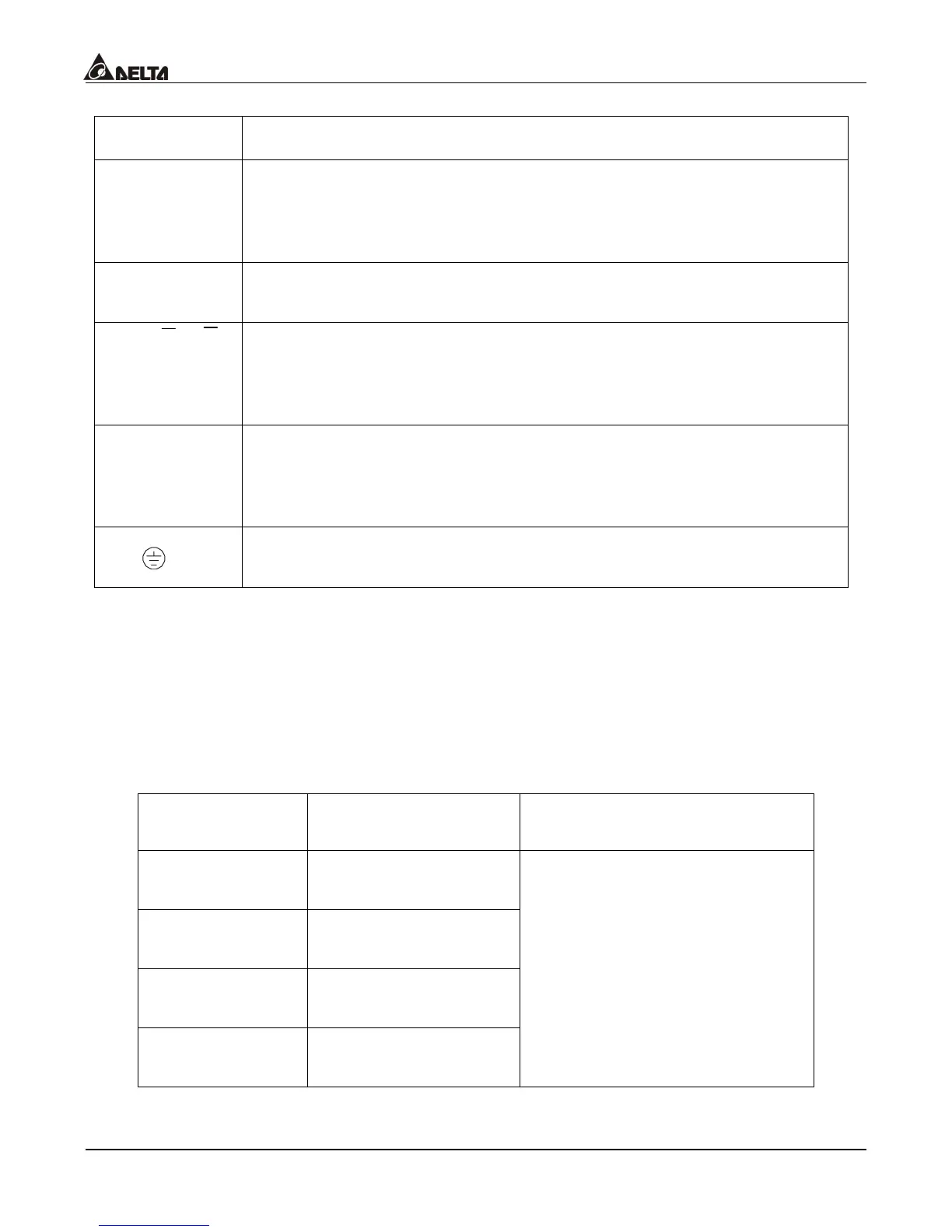
B.4.1 Explanations on the PG Card Terminals
Terminals Explanation
12V
Power Supply of the Encoder: +12V
Output Voltage: +12V±5% 200mA
0V
Common point for the power supply and the signal
A- A, B-B
Encoder signal input (select the output type of the Encoder from FSW2)
Both single-phase input and two-phase input available
Maximum: 500KP/Sec
A/O, B/O
The Encoder signal output
Maximum: DC24V 300mA
Common point for signal grounding
B.4.2 Wiring Notes
1. Use the shielded isolated wire to prevent interference, and do not line up in parallel with
circuits of AC200V or above.
2. The shielded end of the isolated wire should connect to the “DCM” terminal.
3. Recommended wire size: 0.21~0.81mm
2
(AWG24~AWG18).
4. Wire length:
The Output Types
of the Encoder
Maximum Wire Length Wire Gauge
Voltage 50m
Open Collector 50m
Line Driver 300m
Complementary 70m
1.25mm
2
(AWG18) or above

 Loading...

