VFD-V Series
DELTA ELECTRONICS, INC. ALL RIGHTS RESERVED
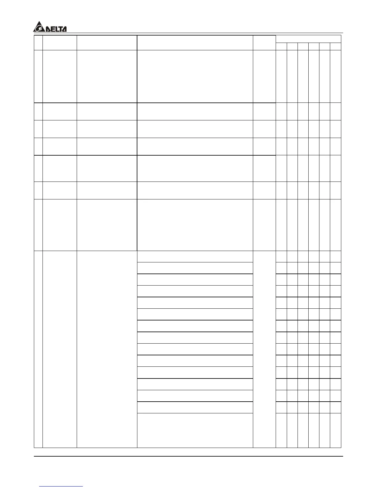
8-14
Control Mode
Parameters Functions Settings
Factory
Setting
VF VG SV SG T TG
a
03-08
(AUI)
Positive/Negative
Bias Mode
0: zero bias
1: value lower than bias = bias
2: value greater than bias = bias
3: the absolute value of the bias
voltage while serving as the
center
0
{ { { { { {
a
03-09
Analog Input 1
Gain (AVI)
-500.0~+500.0% 100.0
{ { { { { {
a
03-10
Analog Input 2
Gain (ACI)
-500.0~+500.0% 125.0
{ { { { { {
a
03-11
Analog Input 3
Gain (AUI)
-500.0~+500.0% 100.0
{ { { { { {
a
03-12
Addition Function
of the Analog
Inputs
0: disable addition function (AVI,
ACI, AUI)
1: enable addition function
0
{ { { { { {
a
03-13
Analog Input
Noise Filter
0.00~2.00 Sec
0.10
{ { { { { {
a
03-14
Loss of the ACI
signal
0: disabled
1: continue operation at last known
frequency
2: decelerate to a stop
3: stop immediately and display
E.F.
0
{ { { { { {
0: output frequency
{ { { { { {
1: command frequency
{ { { { ° °
2: speed
{ { { { { {
3: current
{ { { { { {
4: output voltage
{ { { { { {
5: DC BUS voltage
{ { { { { {
6: power factor
{ { { { { {
7: power
{ { { { { {
8: torque
° ° { { { {
9: AVI
{ { { { { {
10: ACI
{ { { { { {
11: AUI
{ { { { { {
12: torque current command
° ° { { { {
13: torque current estimation
° ° { { { {
a
03-15
Analog Output
Selection
14: exciting magnet current
command
0
° ° { { { {

 Loading...

