3
VFD-V Series
DELTA ELECTRONICS, INC. ALL RIGHTS RESERVED
3-3
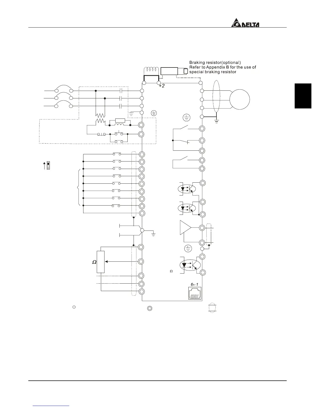
Wiring Diagram 2
15HP(11kW) and above
AVI
ACI
AUI
ACM
4~20mA
-10~+10V
+10V
5K
3
2
1
Power supply
+10V 20mA
Master Frequency
0 to 10V 47K
Analog Signal Common
Main circuit (power) terminals
Control circuit terminals
Shielded leads & Cable
FWD
REV
MI1
MI2
MI3
MI4
MI6
MI5
DCM
+24V
Sw1
Sink
Source
Factory Default:
SINK Mode
FWD/STOP
REV/STOP
Multi-step 1
Multi-step 2
Multi-step 3
Multi-step 4
Digital Signal Common
Factory
default
* Don input voltage directly
to the above signals.
Please refer to wiring
of SINK mode and
SOURCE mode.
R/L1
S/L2
T/L3
Fuse/NFB(None Fuse Breaker)
SA
OFF
ON
MC
MC
RB
RC
Recommended Circuit
when power supply
is turned OFF by a
fault output
R/L1
S/L2
T/L3
E
Multi-function Analog Output
Te r m i n a l
Factory default: Output
Frequency 0~ 10VDC/2mA
U/T1
V/T2
W/T3
IM
3~
MO1
MO2
AFM
ACM
RA
RB
RC
RS-485
Motor
Factory default:
Frequency-Achieving Indication
Factory default:
Driver-Ready Indication
Analog Signal common
Serial interface
1: +EV 2: GND
5:NC
6: NC
3: SG-
4: SG+
DFM
DCM
Digital Frequency Output
Te r m i n a l
Factory default: 1:1
Duty=50% 10VDC
Digital Signal Common
E
E
Please refer to ontrol
Terminal Explanation?
Multi-step 5
Multi-step 6
Shield terminal
MRA
MRC
Multi-function Photocoupler
Output 48VDC 50mA
Factory setting:
Operation Indication
MCM
Photocoupler Common
Output Terminal
Jumper
VFDB
DC chock
(optional)
-(minus sign)
+1

 Loading...

