3
VFD-V Series
DELTA ELECTRONICS, INC. ALL RIGHTS RESERVED
3-7
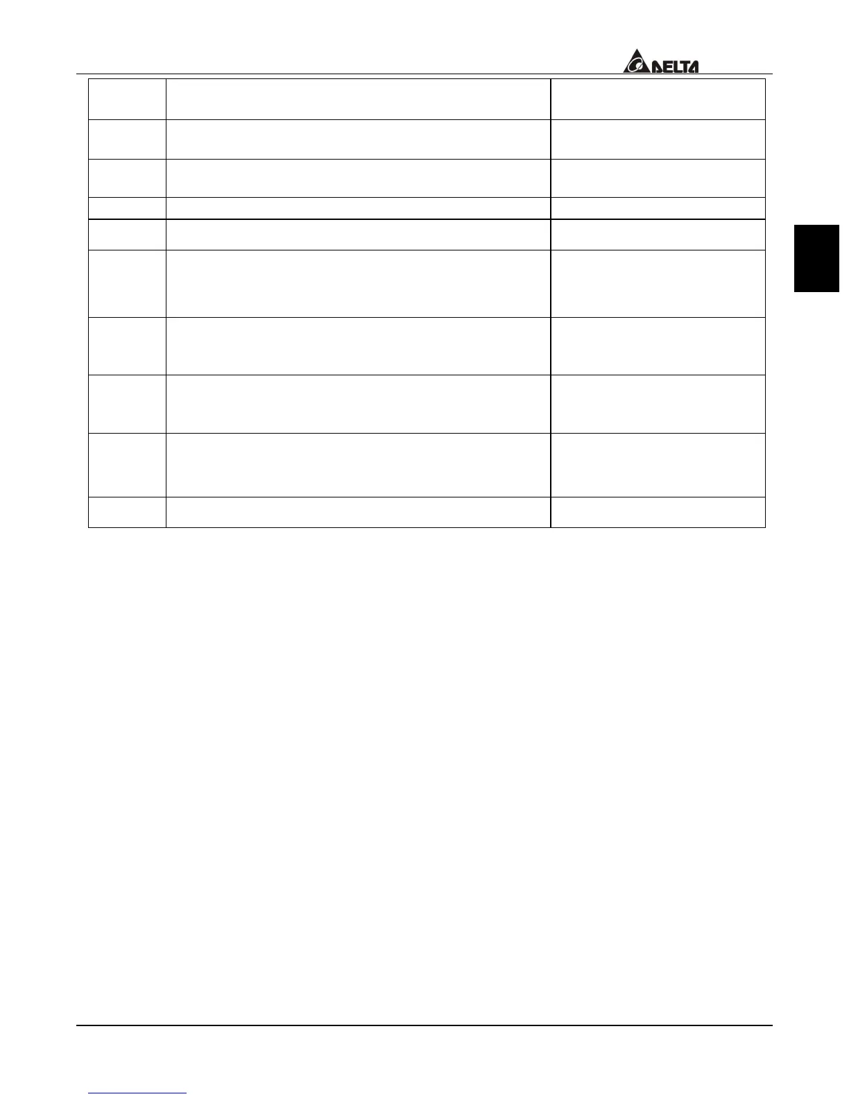
Terminal
Symbol
Explanation on the Terminal Function Factory Setting
MO2 Multi-function output terminal 2 (photo coupler)
(Max 48VDC 50mA)
Set up the frequency
attained
MO3 Multi-function output terminal 3 (photo coupler)
Max 48VDC 50mA
Driver ready
MCM Multi-function output terminal – the common end Max 48VDC 50mA
+10V Auxiliary reference power +10V 20mA
AVI Analog voltage frequency command
The greatest operation
frequency corresponding to
0~+10V
ACI Analog current frequency command
The greatest operation
frequency corresponding to
4~20m
AUI Auxiliary analog voltage frequency command
The greatest operation
frequency corresponding to
-10~+10V
AFM Multi-function analog voltage output
The greatest operation
frequency corresponding to
-10~10V
ACM Analog control signal – the common end
* Analog control signal wire specification: 18 AWG (0.8 mm
2
), cover the isolation
twisted wire.

 Loading...

