EasyManuals Logo
Home>Denon>Receiver>AVR-E400

Denon AVR-E400 Service Manual

Denon AVR-E400
196 pages
To Next Page IconTo Next Page
To Previous Page IconTo Previous Page
Page #162 background imageLoading...
Page #162 background image
TERMINAL
I/O
PULL-
DOWN
5-V
TOLERANT
DESCRIPTION
NAME PIN
VOUT1+ 43 O No No Positive analog output from DAC1
VOUT1- 44 O No No Negative analog output from DAC1
RSV2 45 Reserved, tied to analog ground
AGND2 46 Analog ground 2
VCC2 47 Analog power supply 2, +5 V
RSV2 48 Reserved, tied to analog ground
(1) Open-drain conguration in out mode.
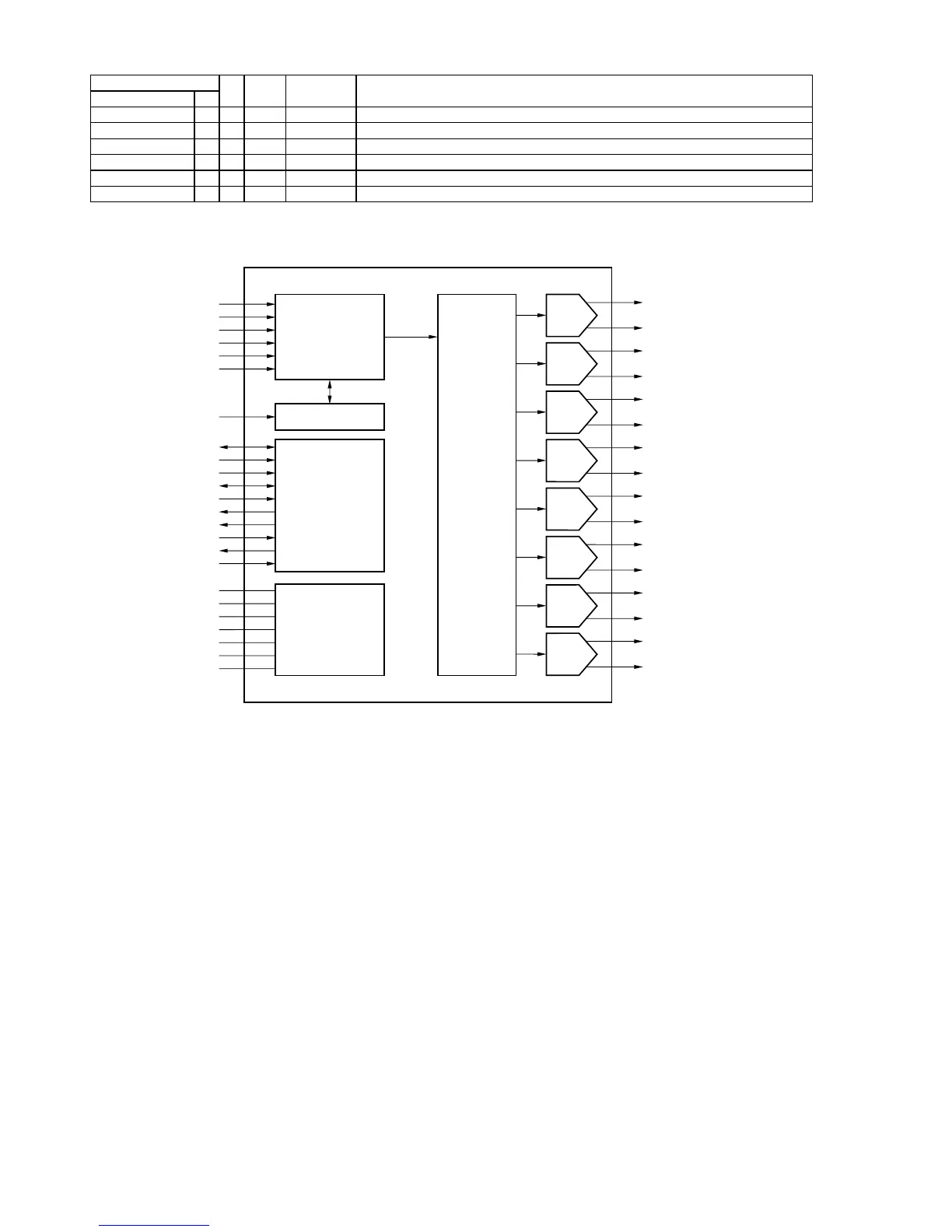
PCM1690 FUNCTIONAL BLOCK DIAGRAM
FUNCTIONAL BLOCK DIAGRAM
DAC
VOUT1+
VOUT1
DAC
VOUT2+
VOUT2
DAC
VOUT3+
VOUT3
DAC
VOUT4+
VOUT4
DAC
VOUT5+
VOUT5
DAC
VOUT6+
VOUT6
AGND2
VDD
DGND
VCOM
VCC1
AGND1
VCC2
DAC
VOUT7+
VOUT7
DAC
VOUT8+
VOUT8
DigitalFilter
and
Volume
PowerSupplyand
CommonVoltage
SCKI
SCKManager
RST
AMUTEO
AMUTEI
ZERO2
ZERO1
MODE
MD/SDA/DEMP
MC/SCL/FMT
MS/ADR0/RSV
TEST/ADR1/RSV
ControlInterface
(SPI/I C/HW)
2
LRCK
BCK
DIN4
DIN3
DIN2
DIN1
AudioInterface
PCM1690
SBAS448AOCTOBER 2008 REVISED JANUARY 2009..............................................................................................................................................
www.ti.com
8 Submit Documentation Feedback Copyright © 20082009, Texas Instruments Incorporated
Product Folder Link(s): PCM1690
162

Table of Contents

Other manuals for Denon AVR-E400

Questions and Answers:

Question and Answer IconNeed help?

Do you have a question about the Denon AVR-E400 and is the answer not in the manual?

Denon AVR-E400 Specifications

General IconGeneral
BrandDenon
ModelAVR-E400
CategoryReceiver
LanguageEnglish

Related product manuals