Chapter 2 Engineering Design of Servo Mechanism
12
Chapter 2 Engineering Design of Servo Mechanism
2.1 Designing the Servo Mechanism
2.1.1 Example of the Mechanism
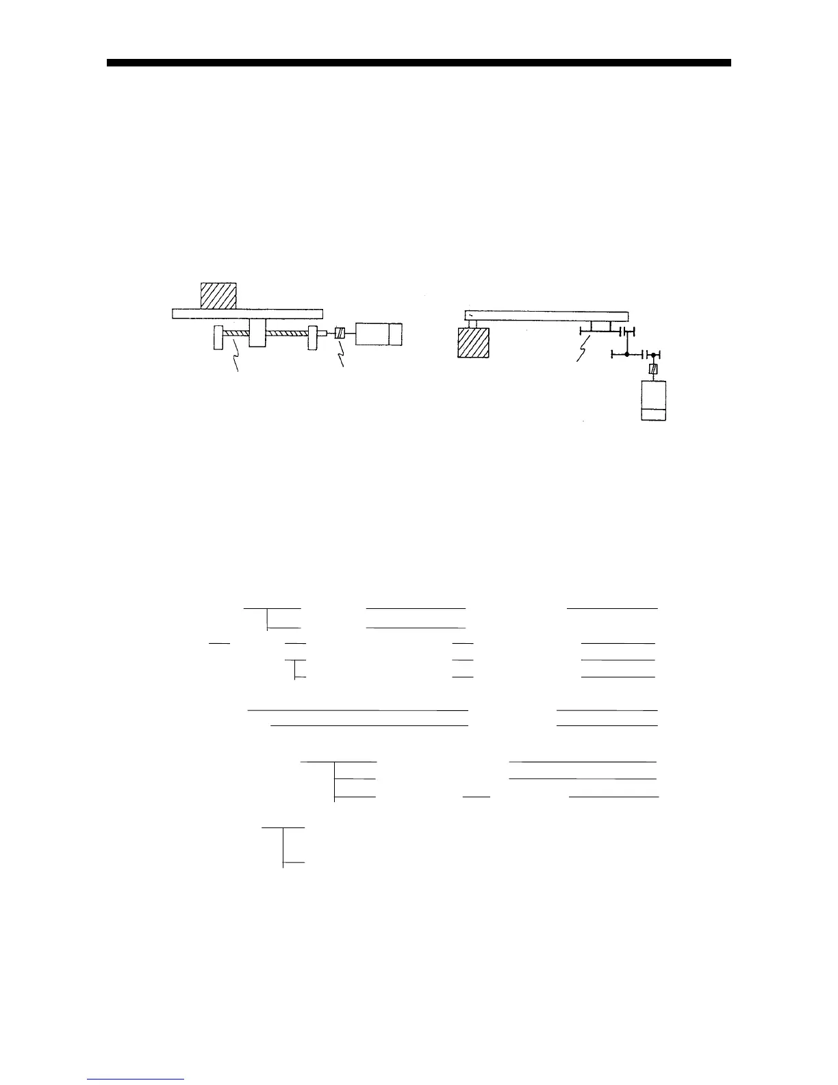
The mechanism is classified into a linear movement section and a revolving arm section as shown
in Fig. 2-1.
(a) Linear movement section (b) Revolving arm
Fig. 2-1 Example of the mechanism
2.1.2 Selection of the Drive System
An appropriate control cannot be performed if a rapid torque fluctuation occurs due to stick slip
or the like.
Typical appropriate and inappropriate examples of the drive system are as shown below:
Ball screw Grinding Backlash small
Rolling Backlash large (Control instable)
Gear Grinding Accuracy grade 1 or higher Backlash small
Cutting Accuracy grade 3 or higher Backlash medium
Accuracy grade 4 or lower Backlash large
Screw shaft Friction large
Harmonic drive Friction large
(Care for selection)
Slide section bearing linear motion bearing
LM guide
Slide bearing
Seal, packing Friction: 20% or less of the rated torque in conversion
into the motor shaft's
Friction: More than 20% of the rated torque in conversion
into the motor shaft's
denotes "Appropriate"
denotes "Conditionally appropriate"
denotes "Inappropriate"
Ball screw, etc.
Load
Moto