Chapter 4 Configuring the Joint Parameters
64
4.7.2 Manual Gain Tuning
You can manage the following parameters for manual gain tuning:
(1) Positioning loop gain
(2) Positioning loop feed forward gain
(3) Positioning error allowance
(4) Speed linear gain
(5) Speed loop integral gain
(6) Torque control filter
(7) Torque offset
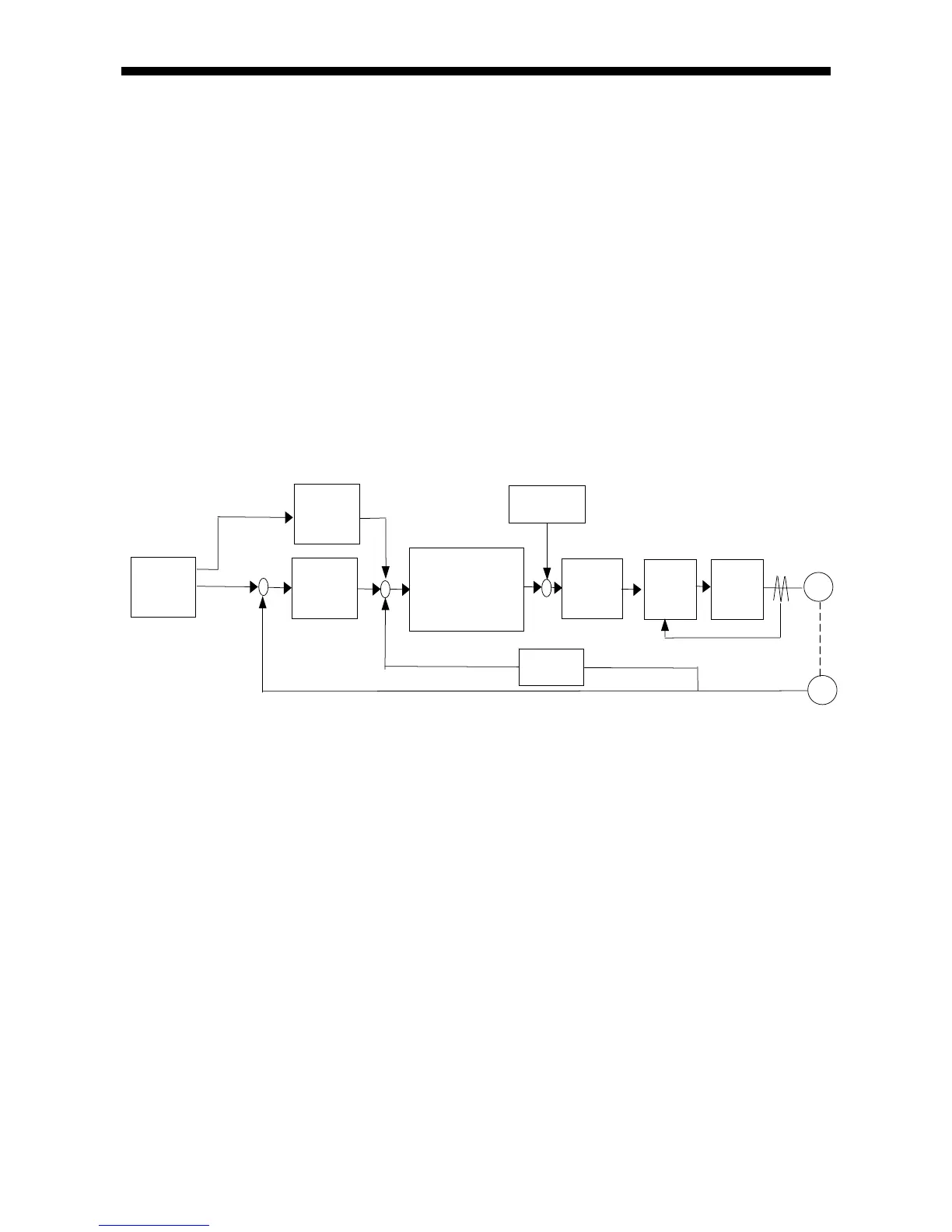
The block diagram for the servo system is shown below.
An electric servo loop system consists of the three feed back systems--positioning
loop, speed control loop, and drive current loop. The inner the loop is, the quicker
response required. If the response of an inner loop is not sufficiently high for an outer
loop, then the overall system response degrades and vibrations or oscillations may
occur in the joint support system.
In this system, the innermost loop is the drive current loop and the outermost loop,
the positioning loop.
You need to do gain tuning for the positioning loop and speed control loop. The drive
current loop is designed to have sufficiently high response for all applications
allowable to the joint support system.
Positioning
path
generator
Position
control
value
Pos. loop
gain
Speed
control
value
Pos. loop
FF gain
Encoder count
Motor rpm
Speed controlle