EN-52 Originalbetriebsanleitung Allgemein
Tighten
Tensioning lever
Clamping
nut
Springs
Axle
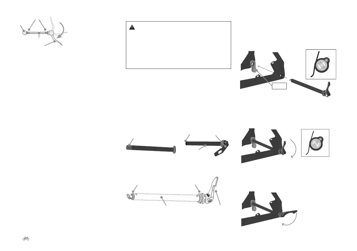
Fig. 116 Quick-release skewer on the wheel
1. Open the tensioning lever by folding it by 180˚. OPEN
should now be visible.
2. Check that the wheel is correctly positioned.
3. Close the tensioning lever by swinging the lever by
180˚. CLOSE should now be visible. The lever should
be very easy to move from the beginning of the closing
movement up to halfway. Then, the force required to
move the lever must signicantly increase until the
lever is very dicult to move at the end.
4. a) If the quick-release skewer closes too easily, the
pre-tension must be increased: Hold the tensioning
lever and turn the clamping nut on the opposite side
clockwise. Check whether the correct pre-tensioning
has been achieved by closing the tensioning lever.
b) If the quick-release skewer is too dicult to close,
the pre-tension must be reduced: Hold the tensioning
lever and turn the clamping nut on the opposite
side counterclockwise. Check whether the correct
pre-tensioning has been achieved by closing the
tensioning lever.
5. Close the tensioning lever. The lever must be
positioned in such a way that it cannot be opened
accidentally.
27.2 Attaching wheels with through-axles
Warning
Serious falls due to loose components.
▪ Close the lever as described. Otherwise, the wheel
may become loose while cycling, and you run the
risk of very serious or even fatal injuries. If you are
unsure, have a specialist workshop show you this
setting.
Through-axles are similar to quick-release skewers. While
quick-release skewers in wheels are pushed through the
axle of the hub, through-axles are themselves the axle.
Unlike quick-release skewers, they have a threaded
connection rather than a clamping nut. Through-axles can
the completely screwed on, or can rst of all be screwed on,
and then tightened using a lever, as on a quick-release
skewer. A further option is to attach the wheel using a
T-piece, which is then secured by means of a lever (e.g.,
R.A.T. through-axle).
Thread
Fig. 117 Through-axle Fig. 118 Through-axle with lever
Thread Tensioning lever
Axle
T-piece
Rotary wheel
Axle Tensioning lever
Fig. 119 R.A.T. through-axle
27.2.1 Mounting a R.A.T. through-axle
1. Insert the R.A.T. axle with the lever in the open
position through the frame/fork and wheel, until the
T-piece at the end of the R.A.T. axle penetrates the
insert on the other side.
Insert
Fig. 120 Insert the through-axle
2. Turn the lever 90° clockwise until the T-piece hits the
insert. The axle should turn easily, and it should no
longer be possible to pull it out of the frame.
Fig. 121 Rotate the lever clockwise
3. Once the axle is in position, ip the lever to tension
the system.
Fig. 122 Tension the lever