27
© 2009 Directed Electronics. All rights reserved.
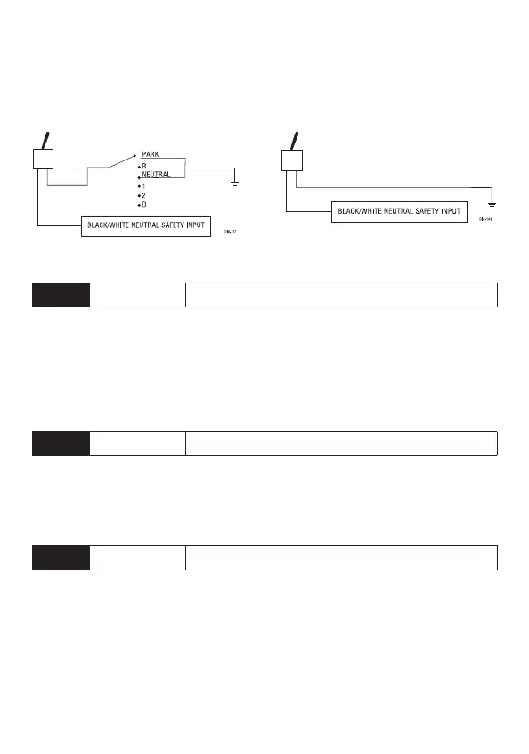
Important: Always perform the Safety Check section of this installation guide to
verify that the vehicle cannot be started in ANY drive gear and that the override
switch is functioning properly.
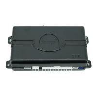
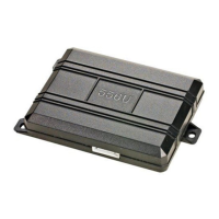
Figure A Figure B
H3/2
VIOLET/WHITE TACHOMETER INPUT
This input provides information to the unit about the engine’s revolutions per
minute (RPMs). In vehicles with conventional coils this wire can be connected
to the negative side of the coil - or to the non-common wire at the fuel injector.
Once connected, you must teach the system the tach signal. (See
Tach Learning
section of this guide.)
H3/3
BROWN (+) BRAKE SWITCH INPUT
This wire MUST be connected to the vehicle’s brake light wire. This is the wire
that shows (+) 12V when the brake pedal is depressed. The remote start will be
disabled or shut down any time the brake pedal is depressed.
H3/4
GRAY (-) HOOD PIN SWITCH INPUT, ZONE 6
This wire MUST be connected to a hoodpin switch. This input will disable or shut
down the remote start when the hood is opened. It will also trigger the security
system if the hood is opened while the system is armed and report Zone 6.