54
© 2009 Directed Electronics. All rights reserved.
Table of zones
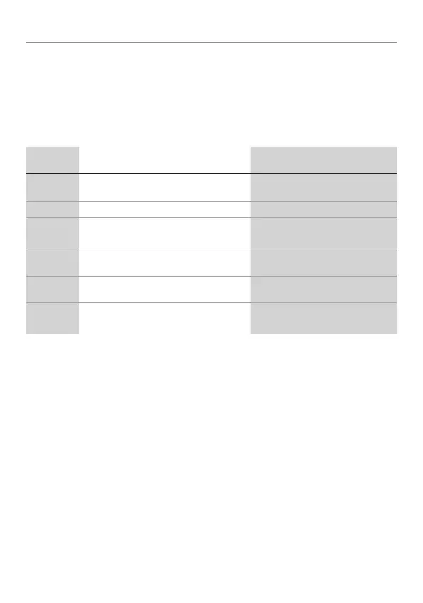
If the alarm is triggered, to find the zone for what caused it to trigger, count how
many times the LED flashes after the alarm is disarmed. Use the Table of Zones
to see which input has triggered the system. It is also helpful in deciding which
input to use when connecting optional sensors and switches.
Zone No. Trigger Type
Input Description
1
Trunk Input BLUE (H1/7)
2
Multiplexed Shock Sensor Input Mux BLUE sensor port wire.
3
Door Trigger GREEN (H1/8) and VIOLET
(H1/6).
4
Multiplexed Shock Sensor Input Mux GREEN wire
5
Ignition
Yellow ribbon harness wire
6
Hood Trigger GRAY on the 6-pin shutdown har-
ness