5. About the engine
100
1) Rotate the crankshaft so that the #1 cylinder piston
may be positioned at the top dead center(OT) and t
he
#
6 cylinder piston may be posiitioned at the valv
e
ov
erlap.
Note) In case of 8/12 cylinder engine, #6. cylinder is posi-
tioned at the valve overlap when #1. cylinder is
positioned at the compression TDC(Top Dead
Center).
Note) In case of 10 cylinder engine, #7. cylinder is posi-
tioned at the valve overlap when #1. cylinder is
positoned at the compression TDC(Top Dead
center).
2) Rotate the crankshaft until the yellow mark of t
he
c
amshaft gear is not shown.
3) Adjust the fuel injection timing with rotating the
flywheel to the engine rotating direction.
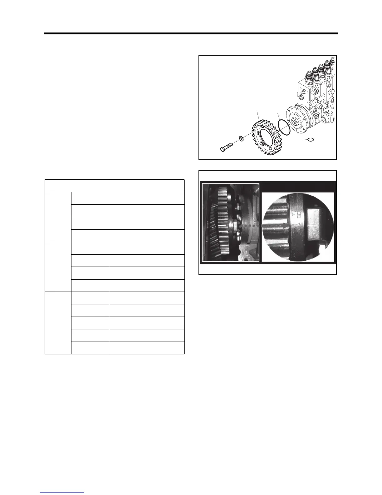
18. Attach the fuel injection driven gear temporarily.
DV2213186A
DV2213171A
1) Attach the driven gear(A) to the fuel injection pump
te
mporarily.
2) Attach the O-ring(B) and (C) to the fuel injecti
on
pum
p.
3) Align the injection timing pointer of the fuel injecti
on
pum
p driven gear with the marking on the cylindrical
surface.
Engine Model
Fuel Injection Timing (°)
DP158L
DP158LCS
23° ± 1°
DP158LCF
18° ± 1°
DP158LDS
23° ± 1°
DP158LDF
18° ± 1°
DP180L
DP180LBS
21° ± 1°
DP180LBF
19° ± 1°
DP180LAS
21° ± 1°
DP180LAF
19° ± 1°
DP222L
DP222LAS
21° ± 1°
DP222LBS
21° ± 1°
DP222LBF
19° ± 1°
DP222LCS
21° ± 1°
DP222LCF
19° ± 1°
 Loading...